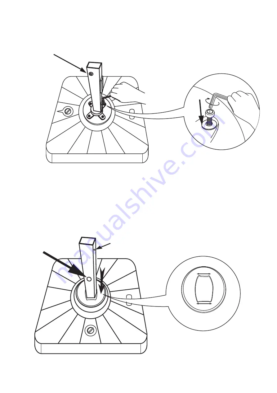
Step 3
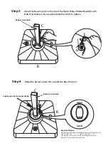
Attach
the Base Pole (C) on the top of the Plastic Water Fillable Stand (B) with
B
olts
(
F
)
&
W
ashers
(
G
),
us
ing
the Allen Wrench (E)
to tighten
Step 4
P
lace
the Swivel Cover (D) around the Base Pole (C).
C
C
B
B
D
E
F
G
Locking hole for threaded knob
Important Notice :
P
ay attention to the size of the middle hole in the Swivel Cover (D).
Side A / Front Side
:
+/- 1.4", Side B
/ Rear Side : +/- 1.7".
Side B of the Swivel Cover (D) and the locking hole on the
Base Pole (C
)
must be
on
the same side.
side B
side A
+/- 1.4”
+/-1.7”
Side B
Bottom crank hole
Bottom crank hole

