background image

5

®

OPERATING INSTRUCTIONS

Congratulations on becoming the owner of a Charnwood Island 
Stove. Your stove has been approved to burn wood logs if it is used 
in accordance with these instructions. It is very important that you 
read and understand these instructions before using the stove. 

Before lighting the stove check with the installer that the work and 
checks described in the Installation Instructions have been carried 
out correctly and that the flue has been swept, is sound and free 
from any obstructions. The stove is not suitable for use in a shared 
flue system.

This stove will not produce significant smoke if well seasoned logs 
of less than 20% moisture content are burnt and these instructions 
are adhered to. Burning wet (>20% moisture content) wood and 
operating the stove in an irresponsible manner may produce smoke 
which is illegal in smoke controlled areas.

Remember that the stove will be hot and that it is made from hard 
materials – ensure that you have good balance before operating the 
fire. Always use the provided operating tool and gloves.

Do not use an aerosol spray on or near the stove when it is alight. 
There is a risk of explosion or flash ignition of the spray.

When using the stove in situations where children, aged and/or 
infirm persons are present a fireguard must be used to prevent 
accidental contact with the stove. 

The stove is suitable for intermittent operation.

FUEL

This stove has been designated to burn wood. Only dry well seasoned 
wood should be burnt on this appliance as burning wet unseasoned 
wood will give rise to heavy tar deposits in the stove, on the glass 
and within the flue. Burning wet unseasoned wood will also result in 
considerably reduced outputs. The wood should be cut and split and 
then left to season in a well ventilated dry place for at least one year 
but preferably two years before use.

Approximate suitable log sizes are:

Island III blu : 550mm(21.6in) long and 100mm (4in) diameter

Log moisture content of less than 20% is recommended.

PETROLEUM COKE IS NOT SUITABLE FOR USE ON THIS 
APPLIANCE. ITS USE WILL INVALIDATE THE GUARANTEE.

This stove is not designed to burn household waste.

DOOR OPERATION

The door handle has been carefully designed so that in normal use it 
may be operated using bare hands. However, if you need to open the 
doors when the fire is running at maximum then the use of a cloth 
or glove may be required. Take care not to touch the doors as they 
will be hot when the fire is burning. Turn the door handle clockwise 
to open, and anti-clockwise to close. The stove is normally run with 
the doors shut. 

Fig. 1. Stove Controls

LIGHTING

On initial lighting, the stove may smoke and give off an odour as the 
silicon paint with which the firebox is painted reacts to the heat. This 
is normal and will cease after a short time, but meanwhile the room 
should be kept well ventilated.

At first only light a small fire and burn it slowly for two hours to allow 
any residual moisture in the flue to evaporate.

Light the stove using dry kindling wood and paper or fire lighters. 
Put the paper, or fire lighters, and kindling in the firebox and cover 
with a few small dry logs. Open the air control fully (see Fig. 1) Light 
the paper or fire lighters. The door may be left cracked open for a 
few minutes to assist the combustion and heat up the firebox more 
quickly. When the kindling wood is well alight add a few more small 
logs, close the door but leave the air control fully open. When the 
flames are established around these logs, load the stove with the 
required fuel load. Maintain the air control at maximum at this stage. 
Once the fire is up to temperature the airwash system will begin to 

Summary of Contents for III BLU

Page 1: ... Operating Installation Instructions AUSTRALIA III BLU ...

Page 2: ......

Page 3: ...OVE 10 HEALTH AND SAFETY PRECAUTIONS 10 FLUE 10 HEARTH AND FIRE SURROUND 10 CONNECTIONS TO FLUES 11 PRE LIGHTING CHECK 11 COMMISSIONING 11 INSTALLATION INSTRUCTIONS 11 CLEARANCES 12 STANDARD HEARTH DIMENSIONS 13 CORNER HEARTH DIMENSIONS 14 FLUE CLEARANCES DIAGRAM 15 STANDARD DEFAULT TRIPLE SKIN FLUE KIT 16 INSULATED ROOM SEAL FLUE KIT 17 INSULATED ROOM SEAL FLUE KIT 18 INSULATED ROOM SEAL FLUE KIT...

Page 4: ...LING THE FIRE Add kindling and paper or firelighters Keep air control fully out and door cracked open Once kindling is alight add smaller logs Keep air control fully out and close door Add larger logs once fire is established Air control can be reduced to minimum MAINTENANCE AND CLEANING GLASS Wipe with damp lint free cloth Any stubborn deposits on the glass may be removed with a proprietary stove...

Page 5: ...t and split and then left to season in a well ventilated dry place for at least one year but preferably two years before use Approximate suitable log sizes are Island III blu 550mm 21 6in long and 100mm 4in diameter Log moisture content of less than 20 is recommended PETROLEUM COKE IS NOT SUITABLE FOR USE ON THIS APPLIANCE ITS USE WILL INVALIDATE THE GUARANTEE This stove is not designed to burn ho...

Page 6: ... the grate from one position to the other is effected using the tool supplied as shown in Fig 2 The grate is put into the open position by moving the tool up until the handle is in the 1 o clock position The grate is put into the closed position by moving the tool down until the handle is in the 5 o clock position To riddle the appliance the tool should be moved between the open and horizontal pos...

Page 7: ...ing most suitable for the type of fuel being used and the draw on the flue MAINTENANCE Cleaning The stove is finished with a high temperature paint which will withstand the temperatures encountered in normal use This may be cleaned with a damp lint free cloth when the stove is cold Should re painting become necessary high temperature paints are available from your supplier or from stove shops Clea...

Page 8: ...alternative means such as a flue access door After clearing any soot from within the stove replace the baffle see Fig 8 It is important to use the correct flue brush for the flue size different types of sweep s brushes are available to suit different flue For prefabricated insulated flues the manufacturers instructions with regard to sweeping should be consulted TROUBLE SHOOTING Fire Will Not Burn...

Page 9: ... been identified if necessary seek professional advice The most common cause of fume emission is a flue blockage For your own safety the flue must be kept clean Fire blazing out of control Check that a The door is tightly closed b The air control slider is fully closed c A suitable fuel is being used d Door seals and air slide are intact Flue Fires If the flue is thoroughly and regularly swept flu...

Page 10: ...hen warm minimum of 12pa 0 05 wg The height of the flue must comply with local building regulation requirements The internal dimensions of the flue MUST NOT BE LESS THAN 175mm 7 The listed flue s construction and installation must comply with the requirements of AS NZS2918 2018 and must also meet local building codes The flue must be suitable for burning solid fuel lined in good condition and at l...

Page 11: ...that the baffle and upper baffle is fitted in the roof of the appliance For location and positioning see Fig 5 Check that the front fence is fitted correctly and that the door closes properly COMMISSIONING Ensure that the rear heatshield extension is fitted to the back of the heaishield part 010 CZEA170 with 2 x 12mm self tapping screws This part must be supplied and fitted to the stove On complet...

Page 12: ...12 CLEARANCES A A B A B C D PARALLEL POSITION COMBUSTIBLE WALLS CORNER POSITION Standard Clearance A 300mm B 471mm C 525mm D 907mm ISLAND III BLU Corner Clearance A 350mm B 706mm ...

Page 13: ...55mm C 300mm D 350mm E 300mm TO WALL MIN DIMENSIONS TO WALL A 1463mm B 955mm C 300mm D 350mm E 525mm VERTICAL REAR FLUE ADAPTOR VERTICAL REAR FLUE ADAPTOR ISLAND III BLU NON COMBUSTIBLE MATERIAL Minimum thickness 24mm Minimum thermal resistivity 0 104m2 K W Installed in accordance with AS NZS 2918 2018 3 3 2 B C D D A B E C D D A B E C D D A ...

Page 14: ...EAR FLUE ADAPTOR CORNER HEARTH A 955mm B 706mm C 300mm WITH VERTICAL REAR FLUE ADAPTOR A 955mm B 706mm C 525mm D 300mm ISLAND III BLU C A B B B B C D D A NON COMBUSTIBLE MATERIAL Minimum thickness 24mm Minimum thermal resistivity 0 104m2 K W Installed in accordance with AS NZS 2918 2018 3 3 2 ...

Page 15: ... top Increase from 1000 min until clear within 3000 of flue top DIMENSIONS IN MILLIMETRES Summary of minimum height of flue sytem exit requirements from AS NZS 2918 2018 More than 3000 More than 3000 600 min 600 min 3000 Any nearby structure Increase as necessary until nothing within 6000 of flue top ...

Page 16: ...16 150 1000 1000 1000 1000 25 600 Cowl Triple skin flue Flashing Optional Decorative Flue Solid OR Mesh Ceiling Ring Dropbox STANDARD DEFAULT TRIPLE SKIN FLUE KIT ...

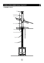
Page 17: ...17 INSULATED ROOM SEAL FLUE KIT 185 1000 1000 1000 25 50 Single skin flue Room sealed flue adaptor Ceiling ring Heatshield Starter length flue Cowl Room sealed flue with locking band STANDARD FLUE KIT ...

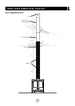
Page 18: ...18 INSULATED ROOM SEAL FLUE KIT FULLY SEALED FLUE KIT 1000 1000 1000 1000 25 50 Cowl Ceiling ring Heatshield Starter length flue Room sealed flue with locking band ...

Page 19: ...mm clearance to any timber to the side and underneath Min 470 Max 620 Cowl Adjustable wall bracket Cleaning access Wall Plate INSULATED ROOM SEAL FLUE KIT REAR FLUE KIT Room sealed flue with locking band Room sealed flue with locking band Room sealed flue adaptor 90 degree tee with cap Wall plate gal Ceiling ring Roof support brace ...

Page 20: ...20 COMPLIANCE DATA ISLAND III BLU COMPLIANCE DATA Compliance plate riveted onto rear heatshield ...

Page 21: ...21 ISLAND III BLU DIMENSIONS ...

Page 22: ...6 R H Door Handle 24 002 AY14 Door Catch Cam 25 008 FFW015 M12 Double Coil Spring Washer 26 004 ST008 Tabbed Locking Washer 27 008 FFN001 M12 Half Nut 28 008 KV13 L H Door Knob 29 008 BW39 S Hinge Pin Set 30 002 PY24 Hinge Post 31 008 AY37 Air Control Knob 32 008 PX95 Riddling Ashpan Tool 33 004 BX048 Tool Holder 34 002 PX89 Riddler Knob 35 004 CY21 Air Bypass Slide 36 004 CY22P Primary Air Inlet ...

Page 23: ...and must be accompanied by proof of purchase Nothing in this guarantee shall affect your statutory rights EXCLUSIONS AND LIMITATIONS This Guarantee does not cover the following Charnwood will not be liable for any consequential loss or incidental loss damage or injury however caused This guarantee will become void if the appliance is not installed by a suitably qualified and is not installed in ac...

Page 24: ...your premier dealer ...

Reviews: