background image

iSMA-B-MAC36NL User Manual 

Version 1.4 

www.gc5.pl 

  Page 12 / 51 

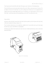
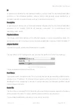
resistor and/or biasing resistors. In the iSMA-B-MAC36NL-RS version 3 position Switch is a 
built-in below terminal connector as shown in the figure below on the right side. 


Figure 7. Switch for termination and biasing for the base (on left) and optional extension port (on right) 


Table 3. Switch Termination and biasing 


Switch position


Biasing


Termination 120 Ω + 

Biasing


END


OFF


ON


BIA


ON


OFF


NONE


OFF


OFF


Summary of Contents for iSMA-B-MAC36NL

Page 1: ...iSMA B MAC36NL User Manual Installation and Start up Guide Global Control 5 S A Warsaw Poland www gc5 pl ...

Page 2: ...on 14 2 4 Detection of the Device Extension 15 2 5 LED Indicators 15 2 6 Mini USB 16 2 7 Local I O 17 3 Start up 17 3 1 Before the Start 17 3 2 SD Card 17 3 3 Factory settings 19 3 3 1 Factory Communication Settings 19 3 3 2 Factory Platform Credentials 19 3 4 First Login to the Controller Platform in Workplace 20 3 5 TCP IP Configuration 23 3 6 Connection to the Console 27 3 7 Controller System U...

Page 3: ... Rules Note Incorrect wiring of this product can cause its damage and may result in other hazards Make sure the product has been correctly wired before turning the power ON Before wiring or removing mounting the product be sure to turn the power OFF Failure to do so might cause electric shock Do not touch electrically charged parts such as the power terminals Doing so might cause electric shock Do...

Page 4: ...nnecting MINI or MIX series I O modules or to integrate with other subsystems Dedicated microSD card stores real time data history and alarms as well as Operating System Niagara Framework and licenses There are 2x USB ports one of them operates as a host and the other one in OTG mode 1 4 Key Features Niagara 4 4 4 6 4 7 and 4 8 Real time programming 2x Fast Ethernet independent 1x RS485 opto isola...

Page 5: ...iSMA B MAC36NL User Manual Version 1 4 www gc5 pl Page 5 51 Figure 1 iSMA B MAC36NL Key Features ...

Page 6: ... input Measurement of resistance from 0 to 1000 kΩ Measurement resolution for 20 kΩ load 20 Ω 12 bit and 1 Ω 16 bit Measurement resolution for PT1000 and NI1000 0 1Ω 16bit Resistance measurement method The voltage divider Dry contact input Output current 1 mA Switching threshold ON 5kΩ OFF 8kΩ Measurement resolution 12 bits default or 16 bits Processing time 10 ms channel 12 bits 140 ms channel 16...

Page 7: ...5 to 95 RH Connectors Type Removable screw terminals Maximum cable size 2 5 mm2 Housing Construction UL approved self extinguishing plastic PC ABS Mounting DIN DIN EN 50022 norm Dimension Width 111 mm 4 4 Length 160 mm 6 3 Height 62 mm 2 45 Table 2 Technical Specification 1 6 Software License Notice This product contains the code covered by the GNU General Public License GPL Note This product cont...

Page 8: ...1 4 www gc5 pl Page 8 51 You may obtain the corresponding open source code of this product by sending an email to rd gc5 pl This offer is valid to anyone in receipt of this information 1 7 Dimensions Figure 2 iSMA B MAC36NL Dimensions mm ...

Page 9: ... pin located next to power supply terminals must be connected to the ground The device has 36x local IO on board 8x Digital Outputs 8DO relay output with max load 3 A 230 V AC 30 V DC 8x Analog Outputs 8AO voltage output 0 10 V DC maximum load up to 20 mA 16x Universal Inputs 16UI temperature voltage current resistive or dry contact 4x Digital Inputs 4DI dry contact inputs or fast counter up to 10...

Page 10: ... EMI Connecting the controller s ground spade lug to nearby earth ground is possible in hardware versions below 2 1 2 3 Communication Bus Connection RS485 The device is equipped with opto isolated RS485 base port which allows connecting the device to the BMS in order to communicate with other devices in the network The optional controller version has an extension as second RS 485 port All rules ar...

Page 11: ...romagnetic switching devices using correct wiring as well as appropriate cable types selection and cable cross sections 2 3 2 RS485 Network Termination and Biasing The transmission line often creates communication problems These problems include reflections and signal attenuation To eliminate the presence of reflections at the ends of the bus cable it must be terminated at both ends with a resisto...

Page 12: ...3 position Switch is a built in below terminal connector as shown in the figure below on the right side Figure 7 Switch for termination and biasing for the base on left and optional extension port on right Table 3 Switch Termination and biasing Switch position Biasing Termination 120 Ω Biasing END OFF ON BIA ON OFF NONE OFF OFF ...

Page 13: ...ion it connects the termination resistor 120 Ω and biasing resistors 680 Ω pull down to ground SG and pull up to 5VDC to the RS485 bus So instead of using additional resistors the termination and biasing can be easily done by simple switch activation Figure 8 RS485 network termination and biasing ...

Page 14: ...munication failures WARNING Only one single device on the network can have biasing resistors connected Connecting biasing resistors on two or more devices on the one single RS485 bus will take the opposite effect increase the number of communication problems Figure 9 RS485 network biasing 2 3 3 M Bus Connection M Bus devices can be connected directly only to the iSMA B MAC36NL M hardware version w...

Page 15: ...lights up orange for 20 ms in the transmit state for sending each package through the extension RS485 port As long as the device sends packages the Communication LED blinks continuously The Communication LEDs ETH1 and ETH2 light up orange in the transmit or receive state when sending receiving each package through the particular Ethernet port As long as the device sends receives packages the Commu...

Page 16: ...UN lights up continuously green Next after the Platform has started up the LED RUN also flashes very quickly If a station exists in a controller after the station has been started up and it operates correctly the LED RUN flashes slowly 1Hz The Alarm LED Δ triangle with an exclamation mark lights up in red color when there is no SD card inserted or there is a problem with the SD card connection rea...

Page 17: ...for SD card which consists of all the software parts needed for hardware management The SD card is not assigned to a particular hardware unit It can be moved to another hardware This function allows for easy hardware replacement Together with the SD card all the parameters such as Communication Settings station Niagara JVM and Operation System are moved License file provides a limited number of po...

Page 18: ...MA B MAC36NL unit For example you might want to remove the SD card from a unit that suffered a hardware failure and use it in a replacement unit Prerequisites All power to the controller needs to be shut down before inserting removing the micro SD card otherwise equipment damage may occur The controller needs to be unmounted from any DIN rail or screw tab mounting as accessing the card uses space ...

Page 19: ...ontroller is restored via clean or update distribution file the default settings are restored Please refer to the Controller System Update chapter for more details WARNING The cleaning deletes the station please save it before update The factory settings can be divided into two groups 3 3 1 Factory Communication Settings IP Address 192 168 1 123 Subnet Mask 255 255 255 0 Default Gateway 192 168 1 ...

Page 20: ...nd it is required to re enter the passphrase and manually restart the station Figures 14 and 15 Passphrase reset 3 4 First Login to the Controller Platform in Workplace WARNING It is highly advisable to install the Data Recovery Service with the first commissioning of the controller See more in the point 3 10 After opening the Workplace Software to log into the controller for the first time please...

Page 21: ...new controller change the type to a regular non TLS platform connection After conversion you should always use the recommended TLS platform connection Host Leave at default IP and type in the default IP address of the new controller the default IP address is 192 168 1 123 Port Leave at default 3011 Credentials Username Type in the factory default User name tridium Password Type in the factory defa...

Page 22: ...www gc5 pl Page 22 51 Figure 16 First login view If the Change Platform Defaults Wizard displays click Next to step through creating a system passphrase creating a new platform account and removing the default platform account as shown below ...

Page 23: ...host and Workbench and displays the Nav Container View 3 5 TCP IP Configuration TCP IP Configuration is one of several platform views Typically you use it to initially configure a remote controller s TCP IP settings Configuring TCP IP communication settings is a task for the systems integrator while initially setting up a controller Perform the following steps Open a connection to the platform ...

Page 24: ...a group of properties For each Ethernet port on the connected platform the TCP IP Configuration platform view provides an expandable Interface in the Image section All compatible iSMA B MAC36NL controllers have two Ethernet ports ETH1 and ETH2 In the TCP IP Configuration view they are listed as Interface 1 eth0 and Interface 2 eth1 Figure 21 Ethernet port configuration As shown above each Interfac...

Page 25: ...rface 1 port of the iSMA B MAC36NL controller F8 DC 7A 0D D6 77 Adapter Enabled Checkbox to specify whether the Ethernet port is usable The top of the TCP IP Configuration view provides the platform s TCP IP host settings Figure 22 TCP IP host setting view These available host fields are as follows Host Name Synonymous with computer name this is a string that can be processed by a DNS server to re...

Page 26: ...er sockets daemon and IPv6 fox multicast sockets If connected to the iSMA B MAC36NL controller the DNS and gateway settings are also host level parameters in the TCP IP Configuration view as shown below For a Windows based host DNS and gateway settings are available under each Interface section Figure 23 DNS gateway view The available fields for iSMA B MAC36NL controllers are as follows DNS Domain...

Page 27: ...h can automate associations between hostnames and IPv6 addresses Included are icon buttons to Add enter the IP address of the server Delete and move Up Down set the DNS search order To save yourself some time when making multiple changes enter all changes before you continue When you finish the configuration click Save The system displays Figure 24 Reboot view Reboot the controller for the changes...

Page 28: ... be downloaded from https www chiark greenend org uk sgtatham putty latest html 3 In the category tree expand Connection branch and choose Serial 4 Set the Serial line to connect to USB COM port in which the controller has been detected It is possible to check which port is in use in Windows Device Manager 5 Set the Configure the serial line fields as shown in the figure below Figure 25 COM port s...

Page 29: ...n you should unpack anywhere on any computer disk Figure 26 Update package file The package contains elements of the system that will be updated as new elements of the system or as newer versions of Niagara operating system modules and the Clean dist file After unpacking run the bat file Figure 27 Unzipped package file The installer will automatically copy all files to the appropriate disk space w...

Page 30: ...iSMA B MAC36NL User Manual Version 1 4 www gc5 pl Page 30 51 Figure 28 Upgrade all out of date of modules ...

Page 31: ...you about the need to update the appropriate controller system component OS NEL JVM Figure 29 Commissioning Wizard with tab informing about the needs to update Note No additional window in the Commissioning Wizard means that the controller has the current version of the system component and there is no need to be update you can cancel the Commissioning Wizard process Go to the last window of the w...

Page 32: ... bog files Px files modules etc The unit s TLS private key information is also deleted In addition installing a clean dist deletes all configured platform users restoring the factory default platform credentials and port 3011 Only TCP IP settings license file and secure communication configuration TLS will be preserved To perform the restore to the default state open a Platform connection to the c...

Page 33: ...function to restore factory values The factory default function causes 1 Removes all users of the platform and restore the factory user tridium with the password niagara 2 Removes the IP network settings and restore the factory IP address 192 168 1 123 3 Removes of all modules and leaving the baja jar module in the version in which the Commissioning Wizard was carried out necessary to connect to t...

Page 34: ...he description on the right you have information about the function of the switch 6 in the S3 dipswitch Switch 6 in dipswitch S3 is used to perform the function of restore factory settings Figure 32 DIP switch view The sequence of restore factory settings is as follows 1 Disconnect the power supply from the controller 2 Pull up the switch 6 in the S3 dipswitch to the ON position up ...

Page 35: ...not be recovered from the iSMA B MAC36NL controller 3 10 Data Recovery Service The Data Recovery Service is the station platform service that provides NV RAM support for iSMA B MAC36NL Providing the platDataRecovery module is installed this service automatically appears under Platform Services Niagara 4 6 and up includes support for iSMA B MAC36NL operation where a controller uses NV RAM non volat...

Page 36: ...uld advise system users of iSMA B MAC36NLs to save often when editing items like Px graphics and Nav files The Data Recovery Service writes current values as they occur to a block of NV RAM When a block is full the service copies it from NV RAM to the controller s flash memory A station that creates rapid COV change of value histories may fill the NV RAM data blocks too frequently triggering a dat...

Page 37: ... save has occurred at least once since the service was created Some NV RAM data recovery blocks have already been flushed to flash Persistent Storage Size is not 0 00 kB Data Recovery Service Editor This Data Recovery Service Editor is the default view of the Data Recovery Service The Data Recovery Service Editor view has the following three main areas Data Recovery Settings Blocks Configuration D...

Page 38: ...ve Limit Period to exceed the Station Save Limit then the service goes into the fault For example more than 5 station saves in 3 minutes period triggers a fault Persistent Storage Size Reflects the total size of all the flushed to flash data block files drdb files that exist in the station s dataRecovery folder in kB Initially this will be 0 until the first NV RAM block flushes to flash It will th...

Page 39: ...total of all flushed to flash data block files drdb files If this limit is exceeded see property Persistent Storage Size the service automatically triggers a station save operation Data Recovery Blocks This area provides expandable bar graphs for each of the NV RAM buffer data blocks to visually represent the current amount of used space overhead space and available free space along with numerical...

Page 40: ...AC36NL User Manual Version 1 4 www gc5 pl Page 40 51 Figure 34 MAC36NL Platform Service Properties view of DataRecoveryService Most of these properties are also on the Data Recovery Service Editor default view ...

Page 41: ...rectly and may have problems with resolution and touch GC5 is not responsible for the proper operation of the iSMA B MAC36NL controller with other HMI panels Note The iSMA B MAC36NL has a built in USB port which supports a display s touchpad Figure 35 Connecting HDMI panel view 3 11 1 Preparation for HMI For convenient use it is recommended to use the Handheld profile for users who support HMI vie...

Page 42: ...b browser works only with HTTP therefore it is necessary to enable HTTP support in Station Config Services WebService by default it is disabled 3 11 2 Update to Support HDMI Port Preparation for using the HMI panel Download the update from the GC5 support site which allows you to support HMI views via HDMI port and is run to install the required files and modules for the appropriate version of Nia...

Page 43: ...ch needs to be added under Station Config Services The iSMAHDMI component contains all the settings which are needed to successfully connect and configure HDMI support Figure 37 iSMA Module The panel HMI connected to HDMI port can work in 3 independent modes Normal mode the panel displays the station data and it is ready for interaction with the user Screensaver mode the panel displays the image c...

Page 44: ...service cannot connect with HDMI the iSMA B MAC36NL software is not up to date or there is a problem with a hardware Service is duplicated HDMI Service is added twice The slots assigned with the Screensaver mode 1 Screensaver Enabled this slot switches on or switches off the Screensaver mode true mode enabled false mode disabled By default the Screensaver mode is active 2 Screensaver Time this slo...

Page 45: ...lt value is 5 minutes Auto Login function Due to the user s requirement to login after a power outage and to ensure better ease of use of the HMI panel the Auto Login function was created Thanks to this function after each power failure the browser automatically login the user and launches the start page according to the navigation file assigned to the user To start the auto login function 1 Enter...

Page 46: ... in another user than the one that has been configured for Auto login This time starts counting down when the login side appears and there is no user activity on the display no touch During the countdown you have the opportunity to log in as another user by clicking on the Change User link Entering any character in the login field cancels the Auto login function If there is no reaction from the us...

Page 47: ... controller and the panel HMI which will cause the panel to be detected by the controller Note Connecting the panel to the HDMI port during power will not detect it 7 During startup the controller platform station and if the HDMI service is not configured in the running station the following image will be visible Figure 40 No HDMI service view 8 After starting the station with the configured HDMI ...

Page 48: ...e 48 51 Figure 41 Login view In the case of the configuration of the Auto Login function the user login fields will be completed automatically along with the activation of the login button and run the start page of the HMI views the following sample view ...

Page 49: ... access it drag your finger from the top of the screen and you will get the following service menu view on the top of the screen Figure 43 Menu view Function buttons fulfil a similar role as in the web browser BACK left arrow return to the previously opened page FORWARD right arrow move to the next page in the case of a BACK action REFRESH circle with an arrow refresh the current page reload HOME ...

Page 50: ...irectly Inconsolata implemented directly Hunkyfonts Sans implemented directly Ubuntu font family implemented directly Niagara default font Adobe Source Sans Pro Note In case of HDMI panels if the user adds text to graphics i e PX file using an unsupported font the outcome will be depicted using the Déjà vu font which may be responsible for moving the whole text to the right The User has an option ...

Page 51: ...he right arrow Figure 45 Transferring fonts view Upon a successful transfer a Transfer complete window pops up Once all the User fonts are successfully transferred go to the Application Director and reboot the controller restart of the station is not enough After the controller is rebooted and the station loaded the HDMI panel will properly depict text with user uploaded fonts ...

Reviews: