DM 54 Chimney System: Load Capacity - Brick Ledge
38
It is relatively simple to calculate the total physical
load on the brickledge resulting from the physical weight of
applied veneers built to code height, however, calculation val
-
ues for load to the brickledge due to wind are site specific and
based on local variables such as wind speed zone, exposure
classification, eave height and roof pitch of the structure, as
well as height of chimney mass exposed to wind.
Important:
The total load delivered into the brickledge is job
specific and will be the sum of:
(1) the physical load from veneers, plus
(2) the load due to wind.
The total of physical load and load due to wind
must not exceed ninety four hundred (9400) pounds.
Notes:
Calculation of wind load requires the services of a
local structural engineer who can evaluate wind load for the
specific structure and site in question.
Do not subject the brickledge to unequal loading
when applying veneers. Build veneers equally on all four sides
of the brickledge.
Brickledge Veneer Finish and Flashing Details:
When applying brick, stone or other masonry veneer
to the Isokern brickledge Fire-Lite good building practices for
masonry veneer work should govern weather-proofing details
and the placement of flashings.
A typical flashing detail would be to field fabricate an
aluminum or galvanized sheet metal flashing, approximately
thirty-two inches (32”)square with a twenty inch (20”) square
hole in it, to serve as an inner flashing. (Figure 65)
Place the inner flashing on the first DM 54 outer cas
-
ing block that fully clears the roof line. Keep the flashing to
about a one-half inch (1/2”) lap onto the top of the outer casing
block. The twenty inch (20”) square hole in the flashing should
fit to the outside of the alignment grooves on top of the DM 54
outer casing. Continue the DM 54 chimney up to the required
termination height.
Once the masonry veneer is in progress the inner
flashing is set into a horizontal joint in the veneer at a level
above all other roof deck flashings, chimney-to-roof flashings
and counter flashings. Weep holes should open to the outer
face of the veneer at vertical mortar joints located at the level
of the inner flashing. (Figure 66)
Where moisture may develop between the DM
54 outer casing and the chimney veneer, inner flashings as
described above will help to divert such moisture to exterior
face of the veneer by way of the weep holes and thereby keep
such moisture from working its way down between the veneer
facing and the DM 54 outer casing and into the interior of the
structure below.
FIGURE 66
FIGURE 65
Summary of Contents for FIRE-LITE series
Page 7: ...Assembled Firebox Smoke Dome Dimensions 36 42 46 7 ...
Page 23: ...23 Interior Masonry Veneer Fireplace Finishes Clearances FIGURE 38 FIGURE 36 FIGURE 37 ...
Page 28: ...DM 54 Chimney Component List Dimensions 28 ...
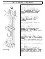
Page 32: ...32 DM 54 Chimney System Lateral Support cont FIGURE 51 FIGURE 52 ...
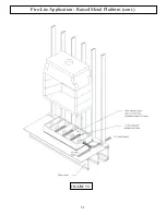
Page 51: ...51 Fire Lite Application Raised Metal Platform cont FIGURE 93 ...
Page 58: ...Notes 58 ...


