FIGURE 68
39
DM 54 Chimney System: Crown Caps
Load Capacity for DM 54 Brickledge:
The sources of load delivered into the Isokern
brickledge are:
(1) the total physical load of brick, stone or other masonry
veneer on the brickledge, and
(2) loading due to the force of wind delivered against the
exposed height of the chimney mass.
The required height of any chimney is governed
by applicable local building codes. The overall finished
height of any chimney varies based upon site-specific
conditions (eg. elevation of roof line, roof pitch, distance
of the chimney from the ridge, etc.).
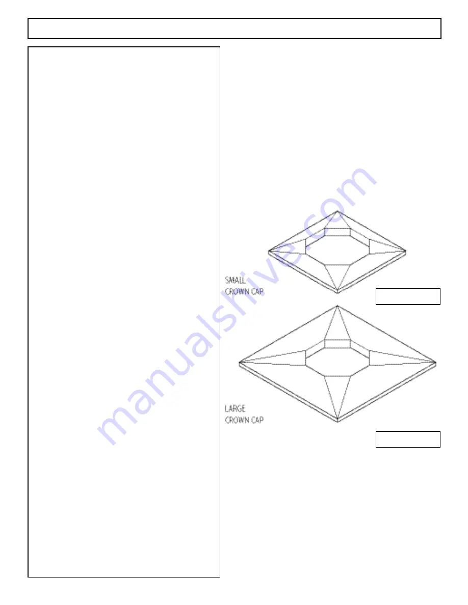
DM 54 Small Crown Cap (Figure 67)
The DM 54 small crown cap is a prefabricated
cement weather cap that measures 26- 1/2” square and 3”
thick. The small crown cap is designed and installed the
same as the large crown cap.
The small crown cap is intended for use where
DM 54 chimneys are to receive thin veneers and cultured
stone that do not require the installation of the Isokern
brickledge. The small crown cap is also suitable where
DM 54 chimneys are to receive a stucco finish.
Other chimney terminations are possible with
DM 54 chimneys. Check local codes for use of custom
chimney terminations and decorative shrouds.
DM 54 Large Crown Cap (Figure 68)
The DM 54 large crown cap is a prefabricated ce
-
ment weather cap for masonry veneer chimneys. The large
crown cap measures 37-1/2” square and is 3” thick at its
center.
The component has an octagonal hole at its center
so that the top inner liner of the DM 54 chimney stack can
pass through it. The crown cap then sits on the top most
DM 54 outer casing block.
To set the large crown cap the last inner liner
should be at least 3” above the last outer casing block in
the chimney stack.
Mortar the top of the last outer casing block. Set
the large crown cap over the inner liner and onto the top of
the last outer casing in the stack.
Caulk or mortar the joint between the octagonal
liner and the crown cap where the liner comes through the
top surface of the large crown cap.
FIGURE 67
Summary of Contents for FIRE-LITE series
Page 7: ...Assembled Firebox Smoke Dome Dimensions 36 42 46 7 ...
Page 23: ...23 Interior Masonry Veneer Fireplace Finishes Clearances FIGURE 38 FIGURE 36 FIGURE 37 ...
Page 28: ...DM 54 Chimney Component List Dimensions 28 ...
Page 32: ...32 DM 54 Chimney System Lateral Support cont FIGURE 51 FIGURE 52 ...
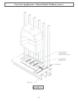
Page 51: ...51 Fire Lite Application Raised Metal Platform cont FIGURE 93 ...
Page 58: ...Notes 58 ...


