Specialty Applications - Two Story Stacked Installations (cont.)
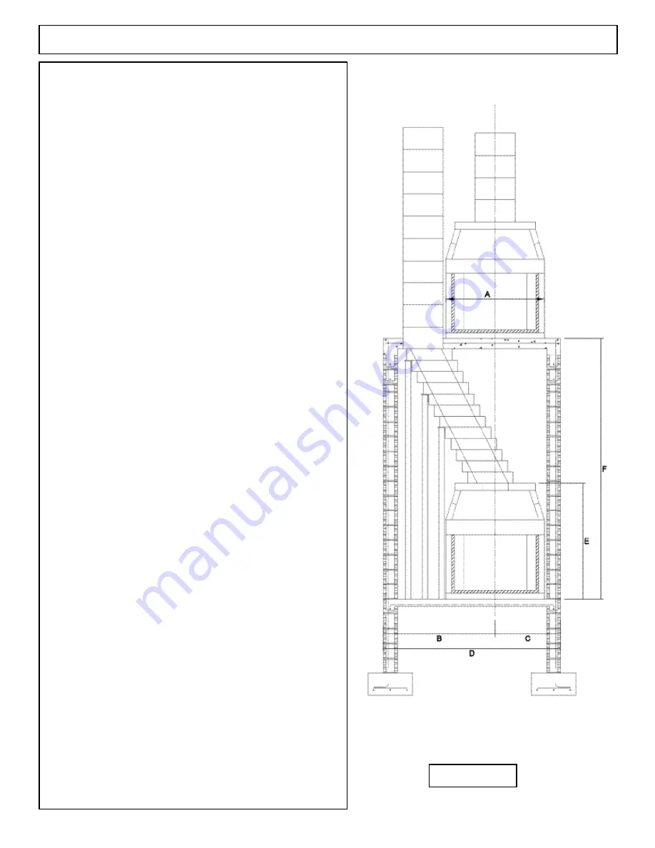
The following chart gives important dimensions needed
when laying out two story stacked Fire-Lite fireplace units. Chart
dimensions assume that both the upper and lower fireplace units sit on
the same centerline.
Upper/Lower A
B
C
D
E
F
36/36
43
51
30
81
70
142
36/42
43
51
33
84
70
142
36/48
43
51
35
86
70
142
42/36
49
54
33
87
70
148
42/42
49
54
33
87
70
148
42/48
49
54
35
89
70
148
48/36
53
56
35
91
70
149
48/42
53
56
35
91
70
149
48/48
53
56
35
91
70
149
Chart Dimension Description:
(Figure 84)
“A”
is the outside width dimension of the Fire-Lite fireplace model
chosen for the upper unit.
“B”
dimension represents distance (taken in the direction
of the chimney offset) from the centerline of the lower fireplace to the
outside face of the eight inch (8”) thick bearing
wall underpinning the upper unit’s support slab.
“C”
dimension is the distance (taken away from the direction of the
chimney offset) from the centerline of the lower or the upper fire
-
place, whichever is the larger plus eight inches (8”) to the outside of
the eight inch (8”) thick bearing wall for the upper unit’s support slab.
“D”
is the outside-to-outside dimension of the two eight inch (8”)
thick bearing walls underpinning the upper unit’s support slab. “D”
is also the width of the upper unit”s support slab and includes the ad
-
ditional space for the width of the DM 54 chimney as it bypasses the
upper unit. “D” is also the sum of “B” plus “C”.
“E”
is the height of the Fire-Lite fireplace chosen for the lower unit
and includes the Isokern three inch thick base plate. “E” is seventy
inches (69 ½” actual) for all of the Fire-Lite models.
“F”
is the dimension from the top of the support slab of the lower unit
to the top of the support slab of the upper unit. “F” dimension is equal
to “E” dimension plus six inches (6”) for the thickness of the upper
slab, plus six inch (6”) thickness of every offset block needed to make
the required horizontal travel distance.
Notes:
If raised hearths are planned for the lower unit then “F”
dimension will increase by the height of the raised hearth at the lower
unit.
In the interest of clarity the drawings on pages 45 and 46
(Figures 83 & 84) of the offset chimney sequence do not show the off
-
set block support columns as required for offset sequences. See page
33 for complete offset support instructions.
Consult local structural engineer for support slab load
calculations.
FIGURE 84
46
Summary of Contents for FIRE-LITE series
Page 7: ...Assembled Firebox Smoke Dome Dimensions 36 42 46 7 ...
Page 23: ...23 Interior Masonry Veneer Fireplace Finishes Clearances FIGURE 38 FIGURE 36 FIGURE 37 ...
Page 28: ...DM 54 Chimney Component List Dimensions 28 ...
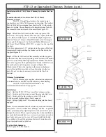
Page 32: ...32 DM 54 Chimney System Lateral Support cont FIGURE 51 FIGURE 52 ...
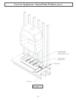
Page 51: ...51 Fire Lite Application Raised Metal Platform cont FIGURE 93 ...
Page 58: ...Notes 58 ...


