__________________________________________________________________________________
6 |
P a g e - S e i t e
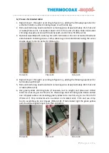
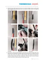
4.
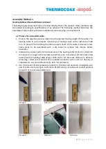
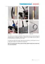
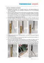
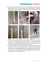
Indicate Contact Point at other end of heated section for electrical termination side
(Picture 7). Indicate next contact point and cut cable directly behind it to get a
maximum of cold lead length (approx. 490 mm). Mark 80 mm and the end of
termination side (Picture 8). Strip outer sheath of cable with knife and remove coiled
wire in stripped section (Picture 9).
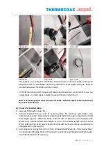
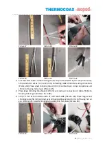
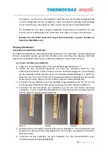
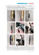
5.
Place large short shrinking tube black centred over stripped cable end (Picture 10).
Use hot air gun to shrink to fit. Use flat pliers to indent shrinking tube between
conductor wires (Picture 11). Strip conductor wire insulation on both ends 7 mm and
use crimp tool to assemble wire end sleeves (Picture 12).
Picture 7
Picture 8
Picture 9
Picture 10
Picture 11
Picture 12
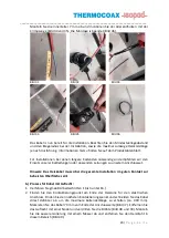
The cable is now ready for installation. Please observe minimum cable spacing and
bending radius for installation as well as maximum indicated circuit length per type.
Refer to product data sheet for additional information.
For field termination with longer cold lead requirements we recommend to use our
supply leads or similar types suitable to use with the termination kit.
Note: The heating cable must be in good contact with the object to be heated over
the entire installation!
Summary of Contents for FG200 Series
Page 26: ......

