©Isothermal Technology
Page 13 of 61
914 millisKanner manual Iss. 1.00
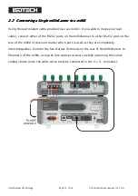
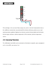
Note the scanner output must be connected to Channel 2 of the milliK
Note the scanner output must be connected to Channel 2 of the milliK
Note the scanner output must be connected to Channel 2 of the milliK
Note the scanner output must be connected to Channel 2 of the milliK
millisKanner
millisKanner
millisKanner
millisKanner Output
Output
Output
Output
Plug Colour
Plug Colour
Plug Colour
Plug Colour
Wire Colour
Wire Colour
Wire Colour
Wire Colour
V-
Black
White
V+
Red
White
I-
Black
Red
I+
Red
Red
Green
Green
N.B. You must use correct plug colour AND wire colour when making the connections.
If you wish to make your own interconnecting cable, use a screened cable with low
dielectric loss insulation such as PTFE or polyethylene (otherwise measurement
performance may be affected). The screen should be connected to the (green) ground
connector of the millisKanner and shell of the Lemo connector. The pin-out used for the
Lemo connectors (looking into the solder buckets) is:


