©Isothermal Technology
Page 21 of 61
914 millisKanner manual Iss. 1.00
3
3
3
3
Connecting Thermometer Sensors
Connecting Thermometer Sensors
Connecting Thermometer Sensors
Connecting Thermometer Sensors
3.1
3.1
3.1
3.1
The Binding Post
The Binding Post
The Binding Post
The Binding Posts
ss
s
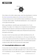
The binding posts accept 4mm plugs, bare wires or spade terminations. Additionally,
they are spaced on 19mm (¾”) pitch so that they can be used with standard 4mm-to-
BNC adaptors (not supplied) for connecting to BNC terminated PRTs.
3.2
3.2
3.2
3.2
Connecting PRTs (4
Connecting PRTs (4
Connecting PRTs (4
Connecting PRTs (4-
-
-
-wire)
wire)
wire)
wire)
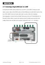
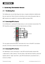
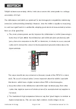
Your millisKanner is optimised for high accuracy, 4-wire resistance measurement. The
PRT should be connected to the chosen input channel, as follows:
R
B
R
B
G
PRT/SPRT
+tc
RED
BLACK
RED
BLACK
GREEN
I
V
The top (green) terminal should be connected to the screen of the PRT’s lead (where
present) to minimise electrical noise picked up by the wires.
3.3
3.3
3.3
3.3
Connecting PRTs (3
Connecting PRTs (3
Connecting PRTs (3
Connecting PRTs (3-
-
-
-wire)
wire)
wire)
wire)
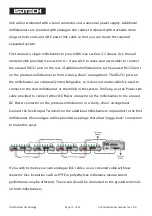
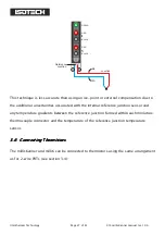
The millisKanner can be connected to 3-wire PRTs and will provide automatically
compensate for cable resistance. The two positive (red) terminals should be connected
together and the ‘single’ end of the 3-wire PRT should then be connected to the I+
terminal as follows:

