MEASUREMENT AND ASSEMBLY MANUAL
Validity of the manual: 1. 6. 2017
17
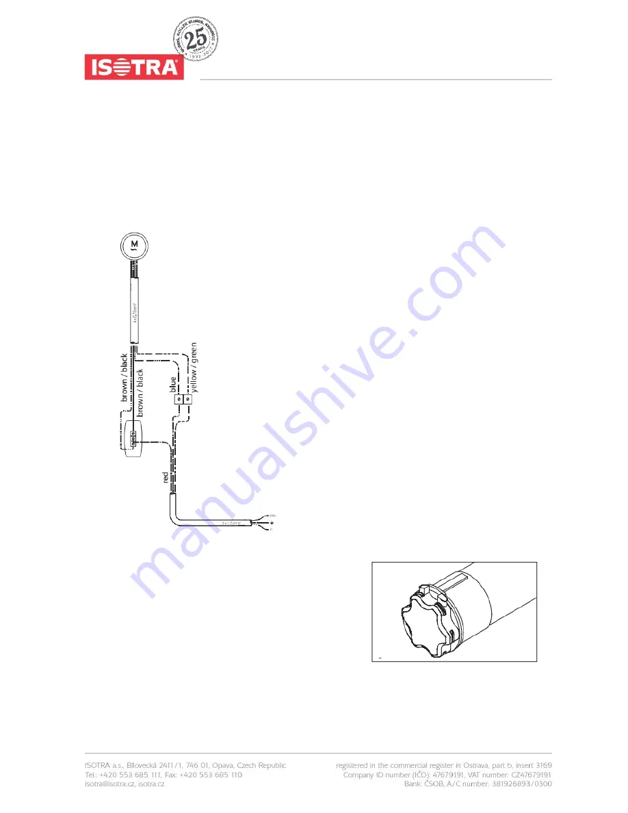
4.2.1. WIRING DIAGRAM FOR A SINGLE POLE SWITCH
The motor has 4 wires. Yellow/green (earth), blue (neutral), brown and black (up and down control). There should be three
wires available from the protected mains circuit. Yellow/green (earth), blue (neutral) and phase wire. Connect the wires
according to the diagram. The phase wire from the electrical mains is connected to terminal L. If necessary, exchange the
brown and the black wires from the motor at the switch so that the arrows on the switch correspond to the up and down
movement of the screen. The two earth wires are connected together by means of separate wire clamps. The same
applies for the two neutral wires.
Connecting and installing the motor:
Lead the motor cable to the control switch until it is out of sight where
possible.
Connect the motor cable and the power supply to the single pole
switch. See above.
Exchange the brown and black wire if necessary so the arrows on the
switch correspond with the movement.
When two or more motors are connected to a single switch, use of
one or more relay boxes is required. Refer to diagram RI2 for making
the connections.
fig. 30
fig. 31


