MEASUREMENT AND ASSEMBLY MANUAL
Validity of the manual: 1. 6. 2017
18
Remark concerning the motor:
If the motor is of the standard LT type, you can continue following the instructions in this manual. For the LS motor, the
stop positions are not set with push buttons but rather with Allen key setting pins (consult the accompanying manual).
If an Altus RTS type is used, consult the instructions that accompany the motor.
4.2.2. CALIBRATING THE MOTOR
– LIMIT SWITCHES
Temporarily connect the test cable to the motor.
4.2.2.1. LOWERING THE SCREEN WITH THE MOTOR
– SETTING THE END POSITION
DOWN
Lower the screen with the motor. Make sure it stops at the correct point and not past the lower stop position, as the screen
could otherwise be rolled up in reverse, causing damage.
The motor limit switches have not been calibrated. Both buttons on the motor have been completely pushed in at the
factory (or press them both in if that is not the case). As a result, the motor will not stop on its own.
Lower the screen until the desired bottom position has been reached. Then put the switch in its neutral position.
Now push the white button (or yellow button, depending on the orientation of the motor) so the button pops out slightly.
The lower stop position has now been set.
4.2.2.2. RAISING THE SCREEN WITH THE MOTOR
– SETTING THE END POSITION UP
Now raise the screen with the motor. Make sure it
stops in time, just below the upper stop position.
Then put the switch in its neutral position.
Now push the yellow button (or white button,
depending on the orientation of the motor) so the
button pops out slightly. The upper stop position has
now been set.
The two stop positions have now been set.
If it becomes necessary to calibrate the motor stop
positions again, the procedure can be repeated by
simply pushing in both buttons. This clears the stop
position settings so new settings can be made by
following the instructions beginning at 4.2.2.
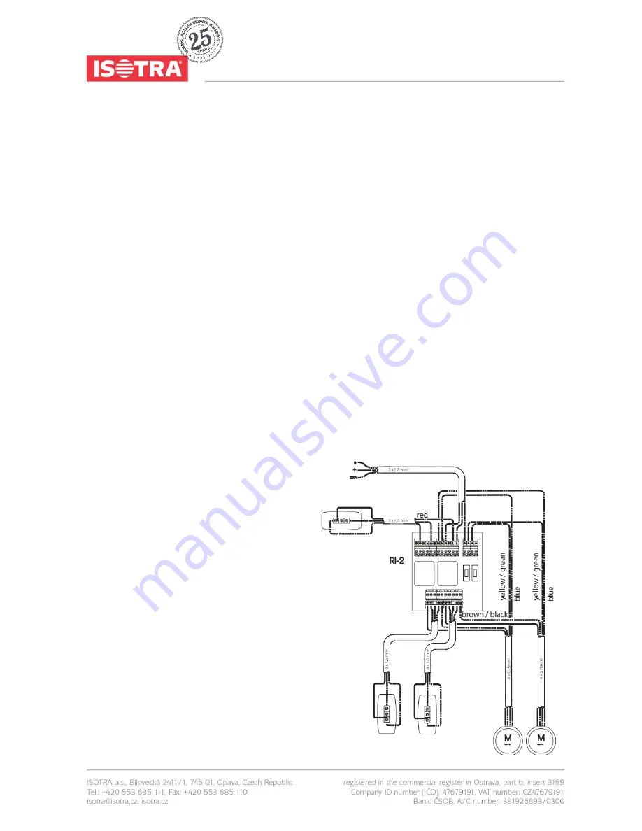
Why use an RI2 relay box?
If several LT or LS motors are operated using the
same switch, you must always use a relay box. If
relay boxes are not used, the system will oscillate
and the resulting high inductive and capacitive
fig. 32


