MEASUREMENT AND ASSEMBLY MANUAL
Validity of the manual: 1. 6. 2017
8
Step 2: Installing the box on the mounting brackets
One mounting bracket per console, as close as possible to the console.
Any additional brackets are mounted in the middle of the box, evenly spaced across its width, and are intended to prevent
wider boxes from sagging.
(1) Push the box upwards into the mounting brackets.
(2) Feed the motor cable through to the inside. Then push the box into the brackets so the slots in the back of the box
engage with the L-profiles.
(3) Next tighten the Allen screws of each bracket. The screws should grip in the slots at the top of the front of the box.
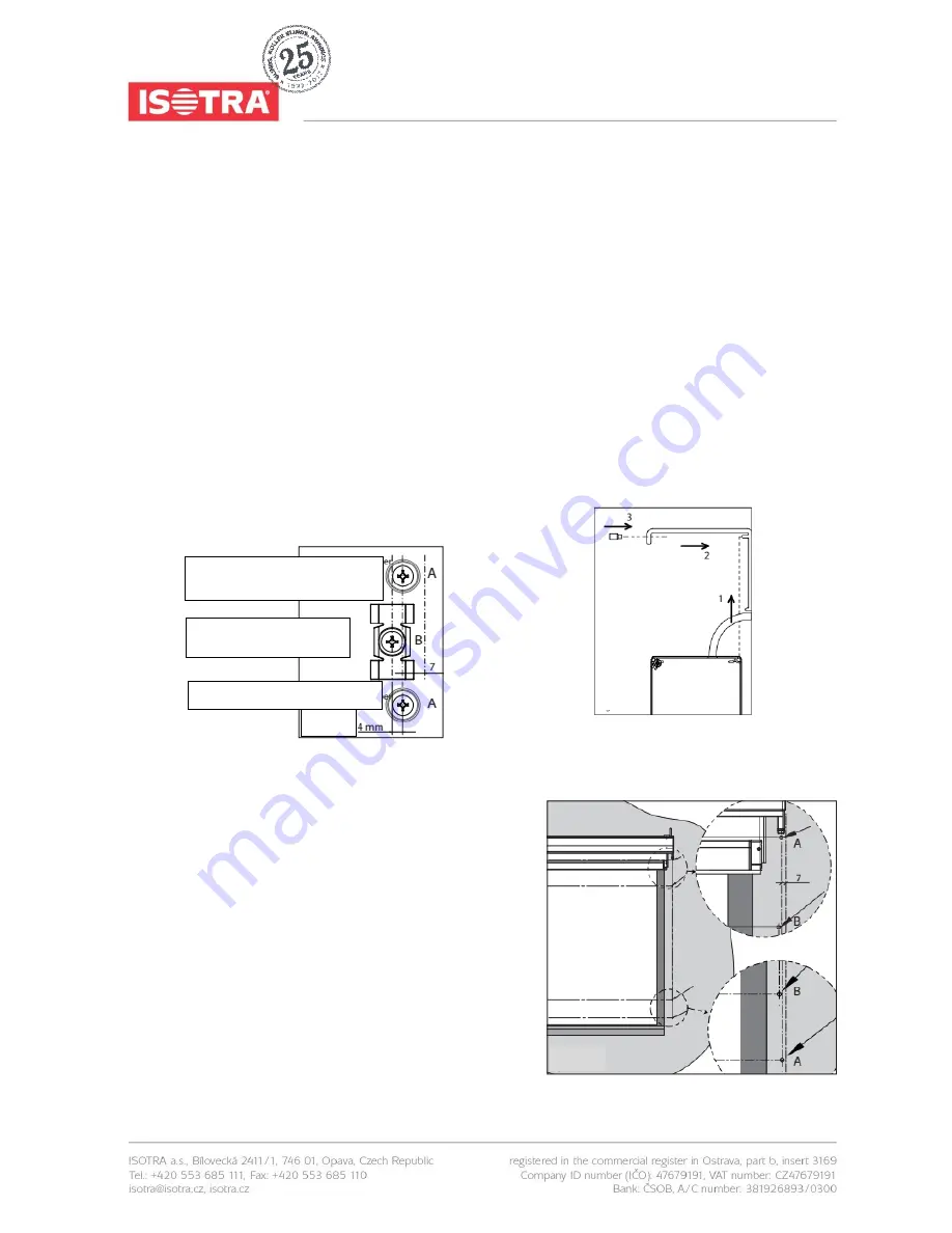
Step 3: Drilling the mounting holes for the guide rails
Mark the holes to be drilled on the wall or on the
mounting surface. Use the pre-drilled lateral guide rails
for thi
s procedure. Drill the holes in the wall (Ø6 mm)
or in the window frame (Ø3.2 mm).
For installation to the wall, insert S6 plugs into the
holes.
Step 4: Installing the guide rails
(1) Affix the clips to the mounting surface. Next slide the guide
rails onto the guide rail pivots of the side consoles. Make
sure the sliding blocks of the bottom slat enter the guide rail
slots correctly and the zipper on the fabric slides into the U-
shaped part of the plastic guide profile.
(2) Screw the guide rails to the mounting surface.
fig. 7
through hole chamber of guide
rail
through hole chamber of guide
rail
of guide rail
for clips
fig. 8
fig. 9


