background image

Page 5

www.123filter.com

   |   (678) 261-7611   |   

Support@123Filter.com


Understanding the Booster Pump and RO Process 


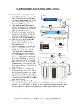
1)


Source water enters the system and 
passes through the stage 1, 2, and 3 pre-
filters. Located between the pre-filters is 
the 

Low Pressure Switch. 

This switch 

turns on when the incoming water 
pressure is 7 PSI or greater.


2)


The 

High Pressure Switch 

turns on 

when the pressure from the pressurized 
tank is below 20 PSI, and turns off at 35 
PSI (e.g. when tank is full). 


3)


When the Low Pressure Switch and 
High Pressure Switch are both on, the 

Feed Water Solenoid Valve

 opens, 

allowing water to the 

Booster Pump.


4)


The source water passes through the 
Booster Pump, bringing it up to 
approximately 80 PSI entering the 
membrane housing. 


5)


Coming out of the RO membrane is a 
pure water port and waste water port. 
The RO water is forced through the 
.0001 micron sized holes of the RO 
membrane, and exits through the one 
way 

Check Valve 

on the membrane’s 

pure water exit port. The water rejected 
by the RO membrane exits through the 
waste water exit port. On the drain line 
before the waste water is disposed is the 

Flow Restrictor,

 limiting the amount of 

drain water allowed out to keep pressure 
in the system. 


6)


The pure water is then routed to the 
pressurized storage tank. As the storage 
tank fills, the tank pressure rises. When 
the pressurized storage tank reaches 35 
PSI, the tank pressure triggers the High 
Pressure Switch off, shutting the booster 
pump and system off. 


7)


When you open the RO faucet, the 
water exits the tank, passes through the FT15 post carbon filter, and is dispensed from the 
RO faucet. As the RO water is dispensed, the tank pressure will gradually drop back down, 
triggering the High Pressure Switch back on to refill the water removed from the tank. 


Summary of Contents for RCC1P

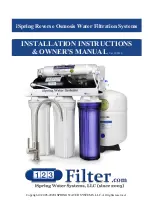
Page 1: ...iSpring Reverse Osmosis Water Filtration Systems INSTALLATION INSTRUCTIONS OWNER S MANUAL Ver 02 2020 Copyright 2005 2020 ISPRING WATER SYSTEMS LLC All rights reserved...

Page 2: ...m has certified by WQA to NSF ANSI Standard 58 for the reduction of TDS as verified and substantiated by test data Please review the attached iSpring RO System WQA Gold Seal Certification or the WQA w...

Page 3: ...alling the RO Faucet 9 Step 3 Installing the Drain Saddle 9 Step 4 Installing the Vertical Filters Stages 1 2 and 3 10 Step 5 Installing theTank Shut Off Valve 10 Step 6 Installing the Reverse Osmosis...

Page 4: ...r pressure 70 PSI otherwise a pressure regulator part no APR70 is required to lower the PSI to the maximum level Operating water temperature range 40 100 F 4 37 C This RO system is NOT designed for HO...

Page 5: ...in moisture 3 Pre Filter Housings and Cartridges Storage Tank RO faucet with installation kit Feed Water Adapter AFW43 4 Color Tubing Set Drain Saddle Tank Valve Housing Wrenches Plumbers Tape Spare O...

Page 6: ...ort and waste water port The RO water is forced through the 0001 micron sized holes of the RO membrane and exits through the one way Check Valve on the membrane s pure water exit port The water reject...

Page 7: ...k sleeve pops out of the fitting when doing this simply pop it back in 4 Insert the tube into the fitting until you reach the mark on the tube You will feel resistance when the tube reaches the small...

Page 8: ...in your sink or counter top 1 It s highly recommended to watch the YouTube video How To Drill Faucet Holes to get a better understanding of the process Depending on what kind of countertop you have yo...

Page 9: ...e pure water line and the flow restrictor doubles as one way valve preventing drain water from entering back into the system Installation Steps Before you begin the installation it is highly recommend...

Page 10: ...ular OFF position Turn on the CWSV slowly and ensure you are getting a proper seal 1 4 Connect the 1 4 RED tubing to the AFW43 Feed Water Adapter with Bushing to convert 3 8 COMP to NPT Step 2 Install...

Page 11: ...ound the hole 3 3 Cut the BLACK tubing end to make a 45 degree angle Slip the plastic nut and front plate on the tubing Insert the tubing into the 1 4 hole in the drain pipe install the back plate and...

Page 12: ...go in a certain direction Make sure the end with the rubber washer faces up thereby attaching it to the housing cap Step 5 Installing Tank Shut Off Valve TSV 5 1 Wrap 10 15 wraps of Teflon tape clock...

Page 13: ...and 9 This is very important to avoid leaking and damage to the O ring 6 6 Place the membrane housing cap back on and hand tighten it then use the housing wrench to tighten it another of a turn Do no...

Page 14: ...efer to How to Use the Compression Fitting 7 7 You may neatly organize the tubing but make sure to leave enough length so the filter system can be moved freely in and out of the cabinet when replacing...

Page 15: ...RO faucet to let it begin filling again 8 8 If your system has a UV filter plug in the UV power and check to make sure the UV light is turning on when water flows through it The UV filter has a Flow...

Page 16: ...epot com This reverse osmosis system contains a replaceable component critical to the efficiency of the system Replacement of the reverse osmosis component should be with one of identical specificatio...

Page 17: ...lter housing off without removing the system from the wall Otherwise you will need to pull the system out lay it down and remove the housings at that point Be careful with the tubing connections when...

Page 18: ...ring is properly seated on the end of the membrane housing as shown in the previous images We recommend replacing the O ring every 3 years to prevent leaking due to an expired or dried out O ring 8 P...

Page 19: ...Kit ICEK The Ice Maker Kit model iSpring ICEK can be purchased separately to feed RO water to your refrigerator for crystal clear ice cubes and great tasting water If you choose to hook up the system...

Page 20: ...herefore not allowing water to pass through See Pump does not start b Incorrect installation Verify all tubing connections c Tank valve is closed Make sure the tank valve is in line with the yellow tu...

Page 21: ...tinuous drain a Keep in mind that it will take anywhere from 1 3 hours for the system to fill the tank from empty and the drain line will be trickling during this time If the drain line continues to r...

Page 22: ...in line with your cold water line and branches off a water supply line to the RO system Can adapt to and cold water lines Feed Water Solenoid Valve ASOW7 Opens the water supply to the booster pump wh...

Page 23: ...ir respective caps Stage 1 See Through Sediment Filter Housing HC12 Transparent stage 1 housing that holds the sediment filter The see through housing allows for the sediment filter to be visually ins...

Page 24: ...nation of the proper equipment necessary to meet your requirements and we do not authorize others to assume such obligation on our behalf This Limited Warranty does not cover any Manufacturer supplied...

Page 25: ...ufacturer warranty and lifetime tech support for all of our products However we do not have the order information from websites other than 123Filter com Amazon Home Depot etc so please be sure to fill...

Page 26: ......

Page 27: ...3020 Trotters Parkway Alpharetta GA 30004 USA 123Filter com For questions comments or technical support please contact us at support 123filter com 678 261 7611 Monday Friday 8 30 a m 5 30 p m EST...

Reviews: