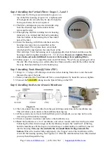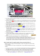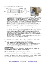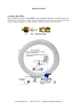
Page 8
Sample Installation
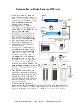
Figure 5
A.
Source water from Feed Water Adapter →
B.
Source water to 1st stage water inlet
C.
Waste water from Flow Restrictor →
D.
Waste water to Drain Saddle/drain pipe
E.
RO water from stage 5 “T” fitting →
F.
RO water to Storage Tank
F.
When the drinking faucet is opened, RO water from the tank passes through E and G →
H.
RO
water to the drinking faucet
*Note,
diagram represents a faucet with non-air gap installation. There is a one valve present on the
pure water line, and the flow restrictor doubles as one way valve preventing drain water from
entering back into the system.
Installation Steps
Before you begin the installation, it is highly recommended that you watch the
video
“iSpring Reverse Osmosis Installation”
on
YouTube.
Note:
If you plan on mounting/hanging the system, it is highly recommended to
include supports under each of the bottom three housings. Supports under the
housings will take the water weight off the housing threads, and ensure the thread strength does not
decay over the years.
Note:
The booster pump (and UV stage if applicable) should remain unplugged until directed.
Note:
Steps 1 – 7 are independent, and can be performed in any order.
Flow
Restrictor
Summary of Contents for RCC1P
Page 26: ......

