background image

T

he


reference


in


surface


TreaTmenT

International

Surface

Technologies

i s t s u r f a c e . c o m

23

DCM600 to 1800 - Instruction Manual

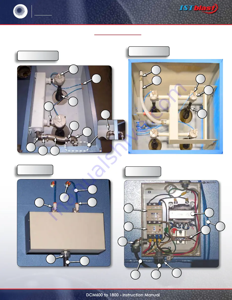
HoW it WorKs

iMPellers & MuFFler

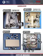
Clogging sYsteM

Clogging system

(DCM 600 & 900)

Clogging system

(DCM 1200 & 1800)

Electrical box

 Figure d1

 Figure d2

 Figure e

 Figure F

1

1

2

2

1

3

3

5

6

8

7

5

1

10

3

9

4

2

4

8

5

4

7

6

6

3

2

4

9

11

Summary of Contents for DCM 1200

Page 1: ...reference in surface treatment International Surface Technologies istsurface com www istsurface com Cartridge Dust Collectors TYPE DCM 600 900 1200 1800 Warranty Safety Operation Service Parts Access...

Page 2: ...intenance 6 GENERAL SAFETY RULES PERSONAL SAFETY UNIT USE AND 6 PERSONAL SAFETY 6 SPeCIFICATIONs 7 GENERAL DESCRIPTION 8 INSTALLATION AND START 8 INSTALLATION AND START UP CONT D 9 INSTALLATION AND ST...

Page 3: ...llers mufflers 22 Clogging system 23 Parts list fig a d1 d2 e 24 Parts list fig F sequential controller 25 Sequential controller specs installation 26 dimensions and size 27 1 0 Installing the DCT1000...

Page 4: ...ot responsible for damage to equipment after it leaves our warehouse 4 Check the equipment received and compare it with the parts you have received If any parts are missing contact the supplier you pu...

Page 5: ...e user in a variety of ways for purposes determined solely by the user No representations are intended or made as to the suitability or engineering balance of the combination of products determined by...

Page 6: ...ting and balance at all times BEFORE CONNECTING THE UNIT to an electric current make sure that the current is the same as that indicated on the identification plate of the collector An electric curren...

Page 7: ...che pRESSION DE TRAVAIL MAXIMUM WORKING PRESSURE 552KPa 80psi lb po2 SPeCIFICATIONs DESCRIPTION DCM 600 DCM 900 DCM 1200 DCM 1800 Cartridge number 2 4 Filtration sqft 562 562 1124 1124 Recycler 13 16...

Page 8: ...sealed Emit a pulse of non sealed cartridges could cause premature failure of the cartridges or reduce the effectiveness of dust The differential pressure indicator shows the difference in pressure be...

Page 9: ...ion is complete refer to the following alert and check the direction of rotation To check the direction of rotation turn on and turn off the engine quickly This will rotate slowly Look inside the slot...

Page 10: ...this may cause serious respiratory problems or death Identify materials to be removed by sanding and get a data sheet of the abrasive used If lead or other toxic material is removed by sanding HEPA f...

Page 11: ...the fan is on the value should be between 0 1 to 3 9 When the unit has new cartridges that value will be close to 0 1 and as and when the cartridge is clogged with dust that value will increase The el...

Page 12: ...value between 2 5 and 3 5 Low limit The value to which the cleaning will stop automatically value between 1 5 and 2 5 High Alarm Value must be reached to activate alarm High limit value 2 Low Alarm Va...

Page 13: ...Safety Data Sheet of the abrasive used Open the cartridge access door Remove the cartridge from the front When the cartridges are removed clean the inside of the dust collector Install the new cartrid...

Page 14: ...Sheet of the abrasive used No pulse is generated Check the pressure gauge if the reading is low check the adjustment of the regulator air supply and check that no supply valve is closed Check that th...

Page 15: ...for continuity Excessive pressure differential The valves do not pulsate properly The supply line gauge pressure differential may be blocked Check and clean The pipes and push in fittings may be block...

Page 16: ...ave a container under the trap to collect dust If you are equipped with a barrel under your dust collection open the lid and empty the barrel System for opening barrels Drain trap The Pamic filter pro...

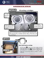
Page 17: ...hen replacing the cartridge Put the spacer 1 on the top of the cartridge with the arrows pointing to the back insert the cartridge into the DCM above the two axles A centered it then turn each axle a...

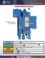
Page 18: ...cleaning process The cleaning process is controlled by the DCT1000 Dust Collector Timer Controller which triggers a series of reverse pulses inside the cartridge to release exceeding dust buildup on...

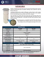
Page 19: ...aintenance Cartridges Check for alarm signal and value displayed on the control panel 2 Replace cartridges as needed 4 monthly maintenance Ducting Check for leaks and wear replace as needed bi annual...

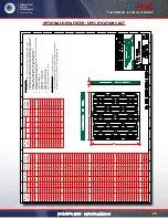
Page 20: ...597 1400 054862 005 25x10x1 24 50 9 50 622 241 610 054862 023 25x12x1 24 50 11 50 622 292 730 054862 024 25x14x1 24 50 13 50 622 343 850 054862 007 25x15x1 24 50 14 50 622 368 910 054862 013 25x16x1 2...

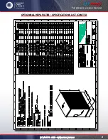
Page 21: ...The reference in surface treatment International Surface Technologies istsurface com 21 DCM600 to 1800 Instruction Manual optionnal hepa filter specifications list cont D...

Page 22: ...313 MOTOR 1 hp 120 V 600 616324 MOTOR 2 hp 575 V 900 616325 MOTOR 2 hp 480 V 616331 MOTOR 3 hp 575 V 1200 616332 MOTOR 3 hp 480 V 616340 MOTOR 5 hp 575 V 1800 616339 MOTOR 5 hp 480 V 2 610526 IMPELLER...

Page 23: ...e Technologies istsurface com 23 DCM600 to 1800 Instruction Manual Clogging system Clogging system DCM 600 900 Clogging system DCM 1200 1800 Electrical box Figure D1 Figure D2 Figure E Figure F 1 1 2...

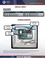
Page 24: ...100VA 4 616933 FUSE 5 616744 CONNECTOR 2269 STOCK DESCRIPTION 6 616572 CABLE 14 3 SJOW 7 616741 CONNECTOR 2524 8 616575 CABLE 14 3 SOOW 9 324571 POLYURTHANE TUBING 1 4 STOCK DESCRIPTION 7 630690 ADAP...

Page 25: ...90 1 8 STOCK DESCRIPTION 4 616770 sealed connector 3 8 5 616535 WATERPROOF cAble 3 8 6 608572 GOYEN VALVE 1 8 120V Figure F parts list figure F sequential controller Sequential controller DCT 1000 dus...

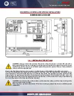
Page 26: ...quire no external inputs and can be used depending on demand through the use of the functionality of cycle time For on demand applications the pressure modules DCP100A 200A optional can be used to enj...

Page 27: ...and maintenance connectors and fuses were left unprotected The design of the open framework of the DCT1000 requires an enclosure that meets the appropriate safety and local code requirements For opti...

Page 28: ...The common solenoid and L2 are connected internally The contacts of the switches connected to the control inputs at the top of the table above should be isolated and only connected to the appropriate...

Page 29: ...onnecting multiple tables timer The two control panels master and slave can have up to 22 channels each The system can be expanded up to 255 channels using master and slave controller cards The DCT100...

Page 30: ...of operating with a continuous cleaning cycle It can be initialized by placing a jumper between the input and the common limit High or by omitting the manual entry of the connection of the ordinary Th...

Page 31: ...side of the module then gently remove the module from the master controller circuit By inserting the module the following procedure should be observed to ensure proper installation Examine the bottom...

Page 32: ...tors Insertion force can damage the connectors Properly aligned the module clicks into place 1 3 5 Maintenance of DCP The pressure module should require very little maintenance in normal operation How...

Page 33: ...user may select either continuous cleaning on demand cleaning or off This switch is supplied factory wired as shown in Figure 4 The switch has a front and rear section The front section consisting of...

Page 34: ...tween one second and 255 seconds The factory default is 10 seconds The display will show the current time off setting when the time off setup mode is entered The value may be changed using the Up and...

Page 35: ...Time Cycles Setup mode 2 9 Down Time Cycles min The Down Time Cycles setup will select a value between zero and 255 minutes The factory default is one minute Selecting zero will disable the operation...

Page 36: ...the triac switch is on This allows a visual correlation between the channel being pulsed and the operation of the solenoid 3 4 Comm Check Indicator The Comm Check Indicator can be found in the upper...

Page 37: ...ill only appear when the master controller is used in conjunction with a slave board Make sure the control cable used in the daisy chain interface is properly shielded from noise Err 4 The master cont...

Page 38: ...voltage circuitry Demand Cycle Mode A process in which the run mode is enabled through the on board pressure module or an external switch such as the Dwyer Photohelic Euro Connector A caged connection...

Page 39: ...R MODULES SLAVE CHANNEL EXPANDER sOLeNO DS ENTR E LIGNE MASTER CONTROLLER INPUT MUST NOT BE CONNECTED normally open contacts CONNECTIONS 4 20mA Series DCP100A 200A Pressure Modules Specifications Inst...

Page 40: ...mA circuit is isolated from ground and other signals The alarm relay contacts are isolated normally open contacts Pressure connections may be made to the stepped hose barbs with either 1 8 or 3 16 I D...

Page 41: ...t the limit to the desired setting Pressing both Up and Down buttons simultaneously and holding for about four seconds will restore the factory default 2 3 High Alarm Setup The operation of the High A...

Page 42: ...the equipment does not disclose any defect in material or workmanship repairs will be made at a reasonable charge which charges may include the costs of parts labor and transportation THIS WARRANTY I...

Page 43: ..._ __ __ __ __ __ __ __ __ __ __ __ __ __ __ __ __ __ __ __ __ __ __ __ __ __ TEL NUMBER __ __ __ __ __ __ __ __ __ __ FAX NUMBER __ __ __ __ __ __ __ __ __ __ PURCHASE FROM __ __ __ __ __ __ __ __ __...

Page 44: ...d the solvent recycling industry mission IST is dedicated to being an innovative and trusted supplier in the conception fabrication and distribution of surface treatment equipment and recycling equipm...

Reviews: