T
he
reference
in
surface
TreaTmenT
International
Surface
Technologies
i s t s u r f a c e . c o m
33
DCM600 to 1800 - Instruction Manual
1.4.3 — Connecting the alarm relay
with the pressure module installed, a relay contact is provided for controlling an external alarm. This relay is a
single-pole contact. It is activated when either of the high alarm limits is exceeded, or if the pressure falls below
the low alarm threshold. The connection is made to the TB5 with a two-pin connector. See connections Figure 2
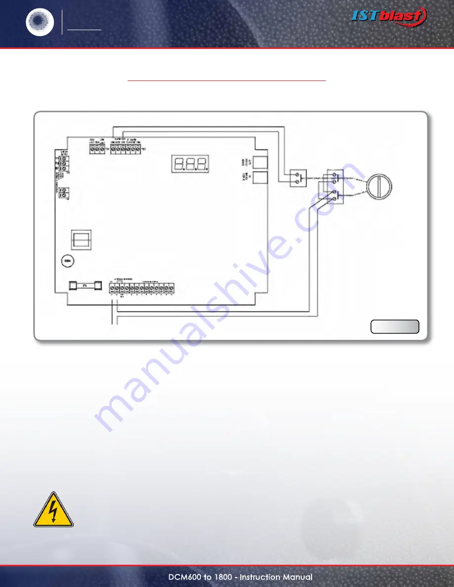
1.5 — three Position selection switch Wiring
An optional mode selection switch is available with the weather Proof enclosure. with this switch the user
may select either continuous cleaning, on-demand cleaning, or off. This switch is supplied factory wired as
shown in Figure 4. The switch has a front and rear section. The front section, consisting of two independent
contacts,controls the power to the board. These contacts must be wired in parallel as shown in the diagram. The
rear section controls the manual override, which when closed will force the system into a continuous must be
reconnected, follow the wiring diagram.
Caution :
Do not interconnect the low voltage manual override leads with the power leads. This
will destroy the control board as well as pose a serious shock hazard.
MASTER
CONTROLLER
L1 L2
line In
Mode selector switch
Wiring Diagram
selector switch to
three positions
section
back
section
front
Continuous
Stop
On
demand
Figure 4
1.0 — installing tHe dCt1000 (Cont’d)

