T
he
reference
in
surface
TreaTmenT
International
Surface
Technologies
i s t s u r f a c e . c o m
8
DCM600 to 1800 - Instruction Manual
general desCriPtion
installation and start
The dust cleaning systems have cartridges, used to draw the abrasive suspended inside the cabinet or
room.
The fan sucks air in from the recycler from 600 to 1800 cfm, depending on the size of the turbine and the
engine. Dust and fine particles pass through the recycler and are retained by the dust and only clean air
is rejected.
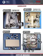
The cartridges are cleaned by a pulse of compressed air blowing the inside of it. The pulse reverses
momentarily the flow of air passing through the cartridges and clearing the dust on the outer surface of
the cartridges. The dust falls to the bottom of the barrel and dust recovery thereafter (page 17).
The interval of the pulses is controlled by a timer inside the control box. The timer control time function
(duration of each pulse) and the stop time (downtime between each pulse). Time as a function should
never be adjusted. The higher the setting time off, the lower the time in each pulse will be short.
Caution :
Do not operate the system cleaning on new cartridges before they are sealed. Emit a pulse of
non-sealed cartridges could cause premature failure of the cartridges or reduce the effectiveness of dust.
The differential pressure indicator shows the difference in pressure between the side coated with dust
and clean the cartridges. The indicator helps determine the appropriate pressure and pulse time setting
off. See page 20.
Install the dust collector in an appropriate place while respecting the laws and regulations in your area.
Allow access to components such as the pressure gauge, fan, door and hatch, the Barrel, the cartridges
and cleaning system.
Connect the electrical connections.
Note: A scheme for firms ISTblast is supplied with your cabinet. After the connection full, always keep the
patterns and all instruction manuals for future reference. wiring junction box must be provided by the
client. Cables and conduits from the main control box to motor connections and the current 120 V control
panel sequence (sequencer module and pressure) must be provided by the user.
The electrical connections depend on the size and number of motor phases. Dust collectors come standard
in this way, refer to your technical representative if your data is different from them.
Dust Collector 600 cfm, 1 hp, 120 V, 1 Ph, 60 Hz
Dust Collector 900 cfm, 2 hp 600 V, 3 Ph, 60 Hz
Dust Collector 1200 cfm, 3 hp, 600 V, 3 Ph, 60 Hz
Dust Collector 1800 cfm, 5 hp, 600 V, 3 Ph, 60 Hz


