background image

T

he


reference


in


surface


TreaTmenT

www.istsurface.com

7


DC/DCM100 to 330 Dust Collector - Instruction Manual & Parts

INSTALLATION

1.  Make sure the equipment is leveled and well grounded. Do not place on a wooden floor or a rubber mat, unless 

a ground wire has been installed. Check with a qualified electrician.

2.  If your dust collector is a “DC” model (without motor), please go to step 4 “DCM” models, with electric motor, 

requires wiring. Check with a qualified electrician.

3.  For 3 phases electric motor, make sure that the rotor’s direction is the same as the black and red arrow located 

on the motor’s case.

4.  For dust collector with the dust collecting drum option, make sure that the drum is properly located under the 

dust collector and that it has been correctly secured to it.

5.  Sound silencer (muffler) (optional) is to be installed directly to the air outlet on top of the dust collector. Use the 

screws included with the silencer adaptor. To allow sufficient air circulation, be sure to have at least 18 inches 

of room around air outlet or muffler.

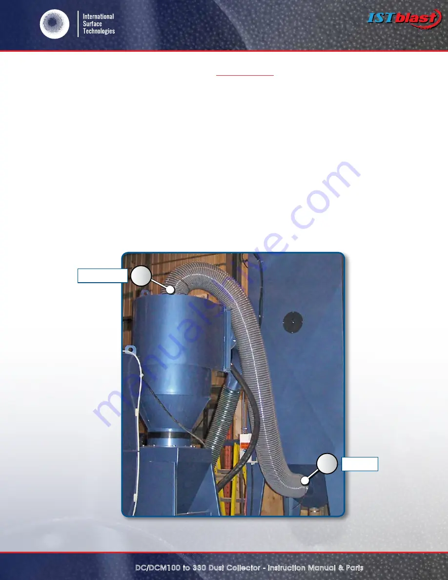
6.  The dust collector should be located on a leveled area near the back of the cabinet, at the right side. Attach one 

end of the corrugated discharge hose to the outlet of the reclaimer (1) and the other end to the inlet located at 

the bottom of the dust collector (2). Secure both ends with the supplied clamps.

7.  Connect dust collector power supply cord to standard 120 Volts (DCM 100 model only)  and 600 Volts ( DCM 160 

/ 230 / 330 models

1

2

Outlet

Inlet

Summary of Contents for ISTblast DC 100

Page 1: ...ence in surface treatment www istsurface com Instruction manual 2019 01 17 DUST COLLECTOR SERIE DC DCM 100 to 330 Warranty Safety Operation Service Parts Accessory Information Registration Form Shown...

Page 2: ...ce 5 GENERAL SAFETY RULES PERSONALSAFETY UNIT USE AND 5 PERSONAL SAFETY 5 muffler optional 6 INSTALLATION 6 INSTALLATION 7 INSTALLATION con D 8 MAINTENANCE 8 MAINTENANCE con D 9 SCHEMATIC OF DC DCM MO...

Page 3: ...possibility of transport damage to the equipment inside 2 Carefully remove your ISTblast dust collector from the shipping carton and skid 3 Check your equipment immediately to ensure that it is free...

Page 4: ...ses determined solely by the user No representations are intended or made as to the suitability or engineering balance of the combination of products determined by the user in his selection nor as to...

Page 5: ...eep proper footing and balance at all times BEFORE CONNECTING THE UNIT to an electric current make sure that the current is the same as that indicated on the identification plate of the collector An e...

Page 6: ...the dust barrel option make sure the barrel is placed under the dust collector and securely connected to it 4 For electric motors operating on 3 phases ensure the rotation will be the same as that ind...

Page 7: ...g drum option make sure that the drum is properly located under the dust collector and that it has been correctly secured to it 5 Sound silencer muffler optional is to be installed directly to the air...

Page 8: ...you should not shake the dust collector s bags This will allow the dust to create a thin layer on the inside of the bag increasing the filtering efficiency It also explains why new bags may leak for...

Page 9: ...e trap to collect the dust picture 3 If you are equipped with the dust drum option simply open the lid with the ring s lever picture 4 and empty dust 3 Never wash dust bags If you have to clean them u...

Page 10: ...The reference in surface treatment www istsurface com 10 DC DCM100 to 330 Dust Collector Instruction Manual Parts SCHEMATIC OF DC DCM MODEL Back side Front side 2 6 7 9 1 9B 9A 3 8 4 5 5A...

Page 11: ...The reference in surface treatment www istsurface com 11 DC DCM100 to 330 Dust Collector Instruction Manual Parts SCHEMATIC OF INTERIOR OF DCM DC 10 13 16 17 19 15 18 11 12 14...

Page 12: ...ence in surface treatment www istsurface com 12 DC DCM100 to 330 Dust Collector Instruction Manual Parts SCHEMATIC OF ELECTRIC BOX AND INTERIOR OF DC DCM Non standard voltage is available 20 23 21 22...

Page 13: ...24 618306 1 2 x 1 2 self adhesive rubber foam 25 610287 Complete door handle 26 610223 Door latch 27 606112 1 8 urethane hose SPARE PARTS FOR DC 100 DCM 100 STOCK DESCRIPTION All sold per foot or per...

Page 14: ...oot 7 610280 8 adjustable air inlet 8 618318 x self adhesive rubber foam 9 Ascabinet Dust conveying hose sold per foot in accordance with cabinet 9A Ascabinet Clamp 9B 601427 600 V Automatic shacker D...

Page 15: ...truction Manual Parts electrical shacker optional installation 4160 Industriel Blvd Laval QC H7L 6H1 CANADA T l 1 877 629 8202 450 963 4400 Fax 450 963 5122 Stock Description 1 917850 timers 2 324560...

Page 16: ...l purchaser transportation prepaid If the inspection of the equipment does not disclose any defect in material or workmanship repairs will be made at a reasonable charge which charges may include the...

Reviews: