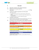
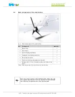
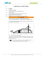
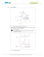
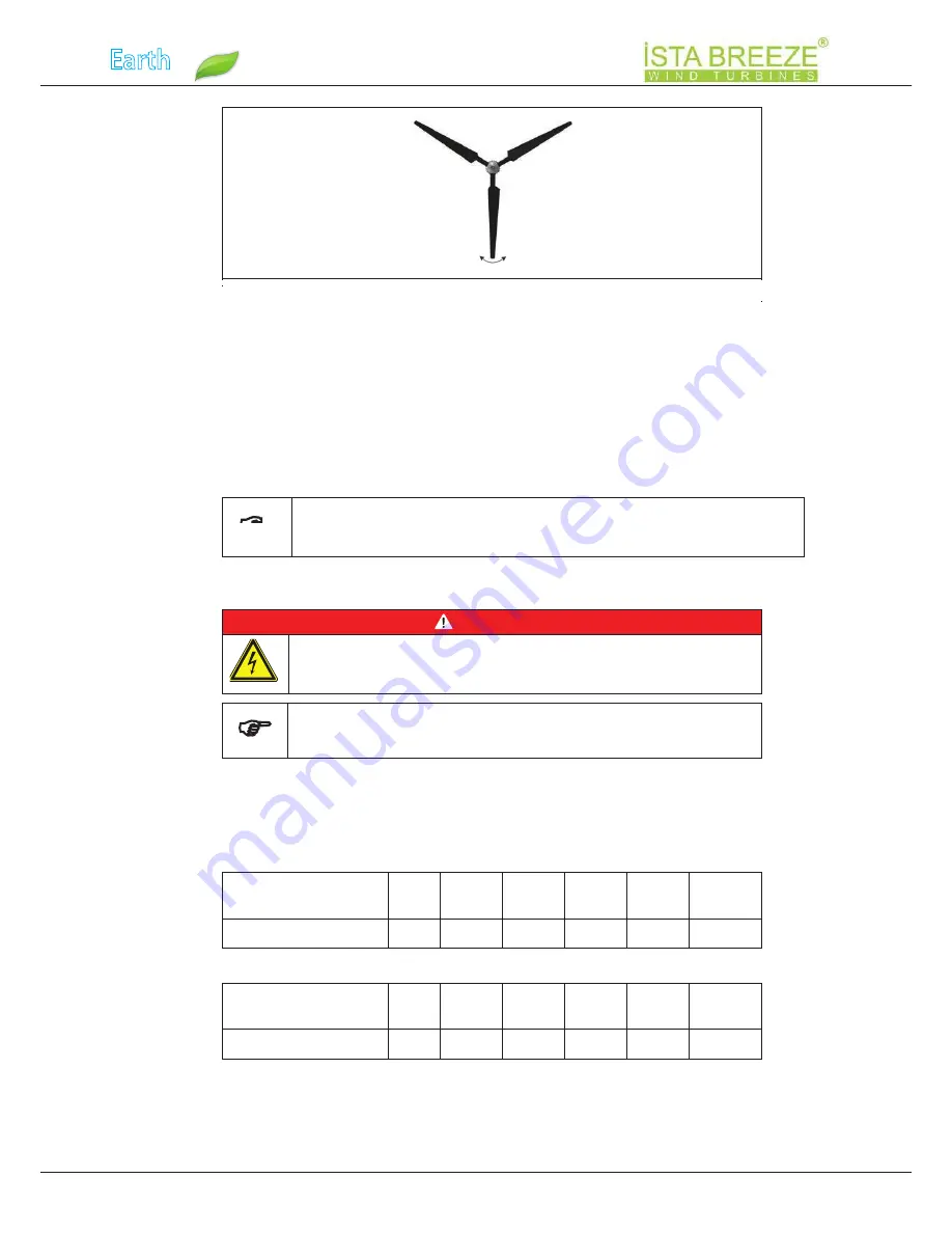
background image

Earth

Safe

Fig. 7:

Balancing the rotor (Y position)

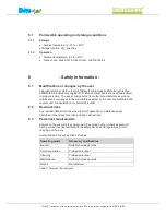
Danger: High voltage!

All work on electrical equipment must be carried out by a qualified 

electrician with the power switched off!

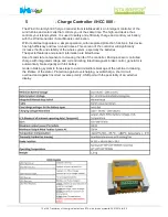
Note: To ensure proper operation, you must use an original iSTA 

Breeze charge controller.

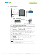
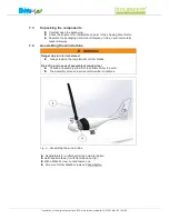
Connect a three-wire cable with a suitable cross-section (refer to Table 9 / 

Table 10) and the required length to the generator.

Make the electrical connections as shown in Fig. 1:.

Connect the charge controller and the transformer as shown in the 

connection diagram (refer to the relevant documentation).
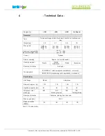
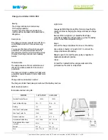
Distance between 

generator and charge 

controller [m]

< 11 11 – 18 18 – 29 20 – 44 44 – 68 68 – 110

Cable cross-section [mm²]

2.5

4

6

10

16

25

Distance between 

generator and charge 

controller [m]

< 11 11 – 18 18 – 29 20 – 44 44 – 70 68 – 113

Cable cross-section [mm²]

2.5

4

6

10

16

25

Move rotor to Y position (see Fig. 7)

Carefully release rotor blade.


Observe in which direction the rotor turns (the heavier rotor blade pushes downwards).


Repeat the process for all three positions to determine which rotor blade is in imbalance.


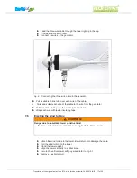
Check repeller for balance

Tighten all screws to 25 Nm.

    Check balance again.


Secure all screws with locking varnish.

Note: The repellers have already been tested for equal weight 
by the manufacturer.

Table 9 Cable cross-section with 

12

 V generator voltage

Table 10Cable cross-section with 

24

 V generator voltage

7

.5

Electrical connections

DANGER!

1

6

of 2

8

Translation of the original instructions iSTA wind turbine system 

2

4

.0

7

.201

8

I00

Summary of Contents for i-300

Page 1: ...SAVE SAVE ENERGY PLANET TRANSLATION OF THE ORIGINAL INSTRUCTIONS Keep handy at the place of use Wind turbine system i 300 i 500 L 500 Air Speed...

Page 2: ...anslation of the original instructions 4 2 2 1 Other symbols used 5 2 2 2 Information 5 2 3 Name and address of the manufacturer and his authorised representative 5 2 4 Warranty and liability 6 2 5 Pr...

Page 3: ...3 of 28 7 6 Erecting the wind turbine 17 8 Normal Operation 18 8 2 Restart after an emergency 18 9 Shutting down the Wind Turbine System 18 10 Maintenance 19 10 1 Safety precautions during maintenanc...

Page 4: ...turbine system 2 2 Conventions used in this translation of the original instructions Safety information is always identified by a signal word and in some cases also by a hazard specific symbol DANGER...

Page 5: ...dicates general information and recommendations 2 3 Name and address of the manufacturer and his authorised representative Name ALTINEL ENERJI DIS TIC ELEK ELEKTRONIK SAN VE TIC LTD STI Phone 0090 212...

Page 6: ...the limits of use described above are considered to be contrary to the intended purpose The manufacturer is not liable for any damage resulting from such use No liability will be accepted by the manuf...

Page 7: ...ind energy into electrical energy 2 Switch switch AC Emergency Stop Button optional optional Type i HCC 800 Generates electrical voltage 12 24 48 VDC The iSTA Breeze charge controller has 40 A fuse pr...

Page 8: ...1 Nose Cover 1 2 Rotor blade 3 3 Hub for holding the blades 1 4 Generator for producing electricity 1 5 Body trage Element 1 6 Tail vane for turning the blades into the wind 1 Note For proper operati...

Page 9: ...i 500 L 500 Air Speed 12V 24V 22A 11A 12V 24V 24V 48V 35A 18A 35A 18A 35A 18A free Weight kg 5 9 6 1 6 6 7 8 Max power Housing material Plastic Plastic Aluminium Aluminium Plastic Hub flange Plastic...

Page 10: ...aking system in three steps to avoid immediate blockage of the turbine Increasing the lifetime of the stator Protection against overcharging overdischarge short circuit overload and against incorrect...

Page 11: ...d If the red light is on it means that the charge controller is braking the wind generator e g when the battery is full or when the wind speed is too high Step 1 Connect the charge controller as it is...

Page 12: ...ns All work on the wind turbine system must be carried out by authorised persons Such persons must be familiar with the safety devices and regulations prior to carrying out the work Authorised persons...

Page 13: ...sufficient height refer to Fig 3 Obstacles are defined as houses hedges trees hills etc When choosing the place of use make sure adequate room is available to tilt the tower and blades if necessary H...

Page 14: ...size and structure of the foundation depend on the soil characteristics Recommendation Ask a qualified structural engineer for advice regarding the optimal design of the foundation Fig 5 Suitable guyi...

Page 15: ...bly at windy sites Choose an assembly site which is sheltered from the wind The assembly process requires calm weather conditions Fig 6 Assembling the wind turbine Repellerblatt 1 mit flacher Seite an...

Page 16: ...110 Cable cross section mm 2 5 4 6 10 16 25 Distance between generator and charge controller m 11 11 18 18 29 20 44 44 70 68 113 Cable cross section mm 2 5 4 6 10 16 25 Move rotor to Y position see Fi...

Page 17: ...efer to Fig 5 Remove the short circuit Fig 8 Connecting the three wire cable to the generato Pull heat shrink tubing over the solder joint and shrink Pull a suitable shrink tube over each wire of the...

Page 18: ...short circuited via the iSTA Breeze charge controller The wind turbine is braked Press the Charge controller OFF button on the iSTA Breeze charge controller Operation is interrupted Press the Charge c...

Page 19: ...Inspect for damage Wind turbine Check the bolts Electrical wiring Inspect the cables for damage Table 11Inspection and maintenance schedule WARNING Danger due to damaged parts Shut down the wind turbi...

Page 20: ...e tower vertically Tower bends in the wind Design a more robust tower Tower foundation has too much clearance Reduce the clearance to a minimum Wind turbine system produces too little power Wind turbi...

Page 21: ...roughly identical in identical wind conditions 5 What is the battery voltage How old is the battery or batteries 6 Which loads are connected to the battery 7 Are solar panels also connected to the ch...

Page 22: ...the tower On the ground Detach the rotor blades from the generator Detach the generator from the tower and disconnect the electrical wiring Where necessary dispose of the individual components in cons...

Page 23: ...EarthSafe Fig 9 Declaration of conformity Translation of the original instructions iSTA wind turbine system 24 07 2018 I00 23 of 28 13 Declaration of Conformity...

Page 24: ...ions iSTA wind turbine system 24 07 2018 I00 Adapter stud 8 Battery 7 10 11 20 21 Cable cross section 16 20 Charge controller 7 10 11 16 18 20 21 Foundation 14 20 Load 10 14 21 Main components Place o...

Page 25: ...EarthSafe 15 Notes 24 07 2018 I00 Translation of the original instructions iSTA wind turbine system 25 of 28...

Page 26: ...EarthSafe 16 Performance Charts 26 of 28 24 07 2018 I00 Translation of the original instructions iSTA wind turbine system...

Page 27: ...EarthSafe 24 07 2018 I00 Translation of the original instructions iSTA wind turbine system 27 of 28 17 Certificates...

Page 28: ...Serkan r t Riemenstr 31 DE 74906 Bad Rappenau 0049 07264 8899740 www istabreeze com ISTA Breeze No part of this document may be copied or reproduced Translation of the original instructions iSTA wind...

Reviews:

Related manuals for i-300