70
ENGINE
1
2
3
4
5
6
7
8
9
10
11
12
13
14
15
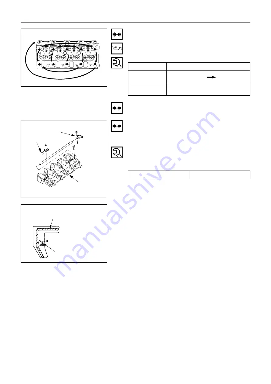
Cylinder head assembly
Lubricate the bolts with oil.
Tighten the bolts in the sequence shown in the illustra-
tion to the specified torque.
N·m (kgf·m/ft. lb)
Push rod
Install the push rods.
Bolt size
Tightening torque
M12
×
1.5
83 – 93
(8 each)
(8.5 - 9.5 / 61 – 69)
60°
〜
90°
M8
×
1.25
24 – 34
(4 each)
(2.5 - 3.5 / 8 – 25)
Rocker arm bracket assembly
Apply liquid gasket to the the bottom of the rocker arm
bracket assembly, being careful not to get any in the
groove around the oil galley as shown in the illustration.
Install the rocker arm bracket assembly making sure the
push rods align with the rocker arms and tighten to the
specified torque.
N·m (kgf·m/ft. lb)
Rocker arm
bracket
Rocker arm
Rocker spring
(Rocker bracket bottom surface)
Apply stem of sealant
Avoid the application
of sealant to this groove.
Oil gallery
{
Tightening torque
8 - 12 (0.8 – 1.2 / 6 – 9)
Fig. 144
Fig. 145
Fig. 146
Summary of Contents for 4LE2
Page 1: ...INDUSTRIAL DIESEL ENGINE 4LE2 MODEL 2003 ISUZU MOTORS LIMITED WORKSHOP MANUAL ...
Page 8: ...GENERAL INFORMATION 5 APPEARANCE 1 MODEL 4LE2 1 Left side view 2 Right side view Fig 2 Fig 3 ...
Page 16: ......
Page 19: ...6 TURBOCHARGER N m kgf m ft lb 16 GENERAL INFORMATION Fig 16 19 28 1 9 2 9 14 21 ...
Page 29: ...MEMO ...
Page 36: ...ENGINE 33 Internal Parts 1 3 1 3 2 7 4 5 17 18 6 15 16 14 Fig 44 ...
Page 37: ...34 ENGINE Internal Parts 2 3 Fig 45 Do not pull out this bolt 20 13 12 9 10 11 8 19 Rear 21 ...
Page 38: ...ENGINE 35 14 1 14 2 15 Internal Parts 3 3 When provided with PTO Fig 46 ...
Page 64: ...ENGINE 61 Internal Parts 1 3 Fig 119 Rear 3 14 2 13 12 11 1 10 9 ...
Page 65: ...62 ENGINE 19 20 18 17 4 5 15 20 7 6 16 8 Internal Parts 2 3 Fig 120 ...
Page 66: ...ENGINE 63 8 1 8 2 7 Internal Parts 3 3 Fig 121 ...
Page 85: ...MEMO ...
Page 91: ...MEMO ...
Page 103: ...MEMO ...
Page 109: ...MEMO ...
Page 111: ...MEMO ...
Page 121: ...PRINTED IN JAPAN IDE 2330 ...


