80
LUBRICATING SYSTEM
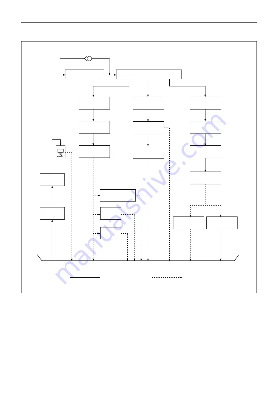
LUBRICATING OIL CIRCULATION DIAGRAM
Pressure feeding
Non pressure feeding
Oil pan
Valve opening pressure 98 kPa (1kgf/cm
2
)
Oil filter
Oil gallery
Main bearing
Crankshaft
Connecting rod
Idle gear bush
Timing gear
Governor
Cylinder head
Rocker arm
bracket
Rocker shaft
Rocker arm
Valve
opening
pressure
440 kPa
(4.5kgf/cm
2
)
Oil pump
Strainer
Piston
Injection pump
Piston
pin boss
Tappet
Valve stem end
Fig. 170
Summary of Contents for 4LE2
Page 1: ...INDUSTRIAL DIESEL ENGINE 4LE2 MODEL 2003 ISUZU MOTORS LIMITED WORKSHOP MANUAL ...
Page 8: ...GENERAL INFORMATION 5 APPEARANCE 1 MODEL 4LE2 1 Left side view 2 Right side view Fig 2 Fig 3 ...
Page 16: ......
Page 19: ...6 TURBOCHARGER N m kgf m ft lb 16 GENERAL INFORMATION Fig 16 19 28 1 9 2 9 14 21 ...
Page 29: ...MEMO ...
Page 36: ...ENGINE 33 Internal Parts 1 3 1 3 2 7 4 5 17 18 6 15 16 14 Fig 44 ...
Page 37: ...34 ENGINE Internal Parts 2 3 Fig 45 Do not pull out this bolt 20 13 12 9 10 11 8 19 Rear 21 ...
Page 38: ...ENGINE 35 14 1 14 2 15 Internal Parts 3 3 When provided with PTO Fig 46 ...
Page 64: ...ENGINE 61 Internal Parts 1 3 Fig 119 Rear 3 14 2 13 12 11 1 10 9 ...
Page 65: ...62 ENGINE 19 20 18 17 4 5 15 20 7 6 16 8 Internal Parts 2 3 Fig 120 ...
Page 66: ...ENGINE 63 8 1 8 2 7 Internal Parts 3 3 Fig 121 ...
Page 85: ...MEMO ...
Page 91: ...MEMO ...
Page 103: ...MEMO ...
Page 109: ...MEMO ...
Page 111: ...MEMO ...
Page 121: ...PRINTED IN JAPAN IDE 2330 ...


