In
the
Min
/
Max
Recording
Hold
mode
,
press
button
to
stop
the
recording
of readings, press
again
to
restart
recording
.
If
recording
is
stopped
,
the
minimum
,
maximum
,
or
present
values
and
analog
display
are
frozen
.
In
the
Min
/
Max
Recording
Ho ld
mode
,
when
a
new
minimum
value
is
exceed
the
actual
minimum
readings
or
a
new
maximum
value
is
overload
,
the
minimum
or
maximum
value
will
held
on
the
display
,
but
the
analog
display
continues
to
be
active
.
In
case
of
in
the
auto
-
range
,
the
mode
is
held
to
just
before
range
.
6
.
Relative Display
:
REL
Button
Press
button
to
enter
the
Relative
Display
mode
,
the
"
REL
"
annunciator
turns
on
,
zero
the
display
,
and
store
the
displayed
reading
as
a
reference
value
.
In
the
Relative
Display
mode
mode
,
the
value
shown
on
the
LCD
is
always
the
difference
between
the
stored
reference
value and the present
reading
.
If
the
new
reading
is
the
same
as
the
reference
value
,
the
display
will
be
zero
.
The
bargraph
is
displayed
absolute
value
,
not
relative
value
.
And
t he
over
-
range
also
occur
against
the
absolute
value
.
In
case
of
the
autorange
,
the range is held just before range.
Press
and
hold
down
the
button for over one second, to exit
the
relative
mode
.
1-8
Summary of Contents for M9803R
Page 1: ...Bench Multimeter Users Manual M9803R...
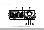
Page 8: ...Instrument Layout Figure 1 1 Bench Multimeter Features Forward 1 2...
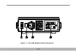
Page 9: ...Figure 1 2 Bench Multimeter Features Backward 1 3...
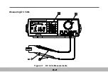
Page 18: ...Measuring DC Volts Figure 2 1 DC Volts Measurements 2 2...
Page 20: ...Measuring AC Volts Figure 2 2 AC Volts Measurements 2 4...
Page 22: ...Measuring DC and AC Amps Figure 2 3 Amps Measurements 2 6...
Page 24: ...Measuring DC and AC Milliamps Figure 2 4 Milliamps Measurements 2 8...
Page 26: ...Measuring Frequency and Adaptive Figure 2 5 Measurement Frequency and Adaptive ADP 2 10...
Page 28: ...Measuring Capacitance Figure 2 6 Capacitance Measurements 2 12...
Page 30: ...Testing Diodes Figure 2 7 Diode Tests 2 14...
Page 32: ...Measuring Resistance and Continuity Figure 2 8 Resistance and Continuity Measurements 2 16...


