8
.
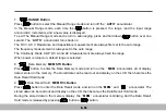
Data Memory
:
MEM
STO
Button
Press
button
to
enter
the
Data
Memory
mode
and
turn
on
the
" "
MEM
annunciator,
all
of
display
data
is
stored
in
the
memory
.
The
stored
data
can
be
read
out
and
display
on
the
LCD
,
then
becomes
the
Data
Recall
Hold
mode
.
9
.
Data Recall Hold
:
MEM
RCL
Button
Press
button
to
enter
the
Data
Recall
mode
,
and
turn
on
the
""
MEM
and
""
annunciator
,
The
stored
data
can
be
read
out
and
display
on
the
LCD
,
then becomes the Data
Recall
Hold
mode
.
During
the
stored
data
in
the
memory
display
,
the
""
MEM
annunciator is blinking. And the Data
Recall
Hold
mode
is
released
by
pressing
button or
button.
Press
button
to
select
the
Manual
Range
mode
and
turn
off
the
""
AUTO
annunciator.
7
.
RANGE
Button
In
the
Manual
Range
mode
,
each
time
the
button
is
pressed
,
the
range
(
and
the
input
range
annunciator
)
increments
,
and
a
new
value
is
displayed
.
To
exit
The
Manual
Range
mode
and
return
to
autoranging
,
press
and
hold
down
button
over
one
second
.
The
""
AUTO
annunciator turns
back
on
.
The
DC V, AC V, Resistance
and
Capacitance
measurement
are
always first set to the auto
range
.
The
frequency
measurement
is
always
set
to
the
auto
range
.
The
Continuity
,
Diode
,
ADP
,
DC
A
and
AC
A
measurement
are
always
fixed
the
range
.
When
power is turned
-
on, default range is selected.
1-9
Summary of Contents for M9803R
Page 1: ...Bench Multimeter Users Manual M9803R...
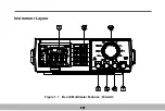
Page 8: ...Instrument Layout Figure 1 1 Bench Multimeter Features Forward 1 2...
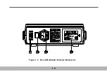
Page 9: ...Figure 1 2 Bench Multimeter Features Backward 1 3...
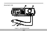
Page 18: ...Measuring DC Volts Figure 2 1 DC Volts Measurements 2 2...
Page 20: ...Measuring AC Volts Figure 2 2 AC Volts Measurements 2 4...
Page 22: ...Measuring DC and AC Amps Figure 2 3 Amps Measurements 2 6...
Page 24: ...Measuring DC and AC Milliamps Figure 2 4 Milliamps Measurements 2 8...
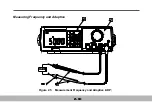
Page 26: ...Measuring Frequency and Adaptive Figure 2 5 Measurement Frequency and Adaptive ADP 2 10...
Page 28: ...Measuring Capacitance Figure 2 6 Capacitance Measurements 2 12...
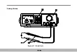
Page 30: ...Testing Diodes Figure 2 7 Diode Tests 2 14...
Page 32: ...Measuring Resistance and Continuity Figure 2 8 Resistance and Continuity Measurements 2 16...


