WARNING
Do
not
attempt
to
measure
currents
in
high
energy circuits
.
The
mA
input
terminal
is
protected
by a
F500mA
/
250V
fast
blow fuse
.
①
.
Turn
the
Selector
to DC and AC Milliamps
.
②
.
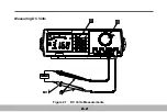
Connect
the
leads
as
shown
.
③
.
is
not
available
in
DC
and
AC
Milliamps
;
all
other
buttons
can
be
used
.
The
DC
or
AC
Milliamps
measurement
is
changed
alternatively
by
each
press
the
button
.
The
DC
and
AC
Milliamps
Measurement
is
as
follows
:
1
.
Insert
the
black
and
red
test
leads
into
the
COM
and
mA
input terminals respectively.
2
.
Select
the
desired
DC
current
range
or
AC
current
range
.
3
.
Turn
off
or
disconnect
the
circ uit
to
be
measured
from
all
power
sources
,
connect
the
multimeter
in
series
with
the
conductor
in
which
the
current
to
be
measured
flows
.
4
.
Turn
on
power
to
the
circuit
under
test
.
Note
the
reading
,
5
.
After
completing
the
measurement
,
turn
off
powe r
to
the
circuit
under
test
,
disconnect
the
test
leads
from
multimeter
.
6
.
The
DC
and
AC
Milliamps
measurement
are
always
fixed
the
range
.
2-9
Summary of Contents for M9803R
Page 1: ...Bench Multimeter Users Manual M9803R...
Page 8: ...Instrument Layout Figure 1 1 Bench Multimeter Features Forward 1 2...
Page 9: ...Figure 1 2 Bench Multimeter Features Backward 1 3...
Page 18: ...Measuring DC Volts Figure 2 1 DC Volts Measurements 2 2...
Page 20: ...Measuring AC Volts Figure 2 2 AC Volts Measurements 2 4...
Page 22: ...Measuring DC and AC Amps Figure 2 3 Amps Measurements 2 6...
Page 24: ...Measuring DC and AC Milliamps Figure 2 4 Milliamps Measurements 2 8...
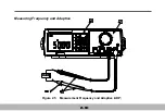
Page 26: ...Measuring Frequency and Adaptive Figure 2 5 Measurement Frequency and Adaptive ADP 2 10...
Page 28: ...Measuring Capacitance Figure 2 6 Capacitance Measurements 2 12...
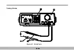
Page 30: ...Testing Diodes Figure 2 7 Diode Tests 2 14...
Page 32: ...Measuring Resistance and Continuity Figure 2 8 Resistance and Continuity Measurements 2 16...

