background image


IMB222 

Rev.4.05 May 2022


EvominiSER  


Transmitter with Modbus RTU 

output signal and I

2

C digital 

sensors or RTD input 


USER

’s

 MANUAL


Summary of Contents for EvominiSER

Page 1: ...IMB222 Rev 4 05 May 2022 1 EvominiSER Transmitter with Modbus RTU output signal and I2 C digital sensors or RTD input USER s MANUAL...

Page 2: ...fixing bracket 17 7 6 Configuration kit 17 8 Order code 18 9 Compatible sensors 19 9 1 Temperature and relative humidity sensor 19 9 2 Temperature sensor with magnetic connector 20 9 3 Sensor for amb...

Page 3: ...gle coil 05 42 12 4 4 Preset single register 06 43 12 4 5 Preset multiple registers 16 44 12 4 6 Modbus exception responses 45 13 EVOSER compatibility 46 13 1 How to set the EVOSER compatibility 46 14...

Page 4: ...tly or indirectly correlated with medical equipment The device must not be disassembled or repaired by unauthorised people Contact your local dealer for any repairs 1 1 Recommendations for workers Whe...

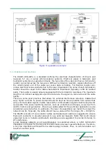
Page 5: ...ity it is an extremely interesting equipment for several applications in industrial environment e g HVAC systems Its M12 connectors allow for a fast and easy cabling feature Furthermore by using this...

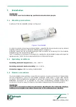
Page 6: ...the model with Pt100 or Pt1000 RTD input 3 2 Operating conditions Installing ambient temperature 40 80 C Installing ambient relative humidity 0 100 Protection degree IP67 according to IEC 60529 3 3 E...

Page 7: ...ct electrical wiring the device is protected only for voltages less than 25 A misconnection with higher voltages will cause a device failure The EvominiSER comes with half duplex EIA RS 485 serial int...

Page 8: ...al interference reduction Cables that carry higher currents to power devices should be kept as far as possible from cables that carry communication signals Cables reserved for communication signals mu...

Page 9: ...9600 104 Thus in this example the terminating impedance is not strictly necessary However whenever the terminating impedance is required a resistor must be inserted in the last node from the master be...

Page 10: ...dimensions The transmitter mechanical dimensions are shown in Figure 6 5a 5b Figure 6 mechanical dimensions EVO032 EVO040 Figure 1a mechanical dimensionis ESTP Figura 2b mechanical dimensions EOSI me...

Page 11: ...th ERR indication for either memory errors or boot mode operation white LED with TX and RX indication serial and batch number The following features are for the EvominiSER RTD model only Input RTD Pt1...

Page 12: ...ter and the sensor For EVO032 and EVO040 models check that the ferrule of the device is well screwed to the sensor if the problem persists contact technical assistance If the Fast start option is acti...

Page 13: ...22 Rev 4 05 May 2022 13 7 Options 7 1 Isolator Serial repeater It allows for signal isolation and amplification between the RS485 serial port and the power supply of the EvominiSER Measurements are in...

Page 14: ...ables with larger diameter to sustain higher currents The two pairs of cables are shielded using an overall aluminum foil and a drain wire allowing for an easy connection with M12 connectors An extern...

Page 15: ...51 7 3 Extension cables with M12 connectors Several extension cables are available with different lengths The cable is described in chapter 7 2 and has two M12 5 pole connectors overmolded straight or...

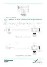
Page 16: ...digital transmission with integrated extension cable This model integrates the extension cable on one side It is suitable for connection with the master unit of the Modbus network all the measurement...

Page 17: ...te 7 5 Wall fixing bracket The EvominiSER device together with its probe can be fixed to the wall with this its bracket Ordering code AMEC028 7 6 Configuration kit This kit is useful for programming E...

Page 18: ...Modbus RTU output input for RTD Pt100 Pt1000 power supply 9 32Vdc IP67 M12 male connector for output M12 female connector for input sensor EOSI Programmable Modbus RTU digital output RS485 temperature...

Page 19: ...the connected sensor at power on all LEDs will be permanently on after the transmitter initialization The EvominiSER RTD model can be connected with RTD sensors Pt100 Pt1000 RTD temperature sensor Pt1...

Page 20: ...8 The mechanical dimensions of the device are reported in Figure 9 Figure 8 sensor mechanical dimension Figure 9 device mechanical dimension 9 2 Temperature sensor with magnetic connector Compatible f...

Page 21: ...nsor mechanical dimensions are reported in Figure 11 Figure 11 Sensor mechanical dimensions 9 3 Sensor for ambient ligh Compatible firmware release x xx 3 where x xx can be 1 00 o newer Connection 4 P...

Page 22: ...Typical accuracy see Figure 12 Temperature compensated Sensitivity spectrum close to human eye photopic curve V see Figure 13 Figure 12 Sensor accuracy Figure 13 Spectral response Figure 14 mechanical...

Page 23: ...ct of the new inserted value is immediate while others in which a device reset is necessary to enable the new inserted value In the following tables the range of acceptable values for each register ha...

Page 24: ...been chosen This value is saved into non volatile memory and in order for its modification to have effect the device should be restarted Admissible values 0 corresponds to no parity bit selected 1 co...

Page 25: ...only Copy of register 40001 40071 Device temperature minimum peak Read only x 40072 Device temperature maximum peak Read only X 40073 BOOT FW version Read only The effect of parameter s modification i...

Page 26: ...s multiplied by 15 For example if a value of 1 is read at address 67 and a value of 3 is read at address 68 the device is working for 16384 hours This value is saved into non volatile memory Address 4...

Page 27: ...ignaled by the flashing of the ERR LED in these conditions functionality is not guaranteed and the device could break Address 40072 Device temperature maximum peak R Only for EvominiSER RTD The maximu...

Page 28: ...10 C ESTP 500 C EOSI Correction low reference As User Span Low Correction high reference As User Span High Correction low measure As User Span Low Correction high measure As User Span High One point o...

Page 29: ...52 Sensor type R The type of sensor connected to the EvominiSER device is set in this register the compatible sensors are listed in the Range of values column The sensor types from 1 to 9 are digital...

Page 30: ...value in m at 0 C R0 For ESTP and EOSI models with integrated sensor this value can not be changed For the EVO040 model a value between 99 000 101 000 ohm can be set for the Pt100 and between 990 000...

Page 31: ...del Address 40208 correction high reference R W This parameter is expressed in tenths of degree and it is valid only if register 40206 is equal to 1 or 2 It identifies the upper reference temperature...

Page 32: ...rrors R This register is a copy of 40070 Address 40002 Temperature R Detected temperature values expressed in tenths of Celsius degree For example a value of 100 corresponds to a temperature of 10 0 C...

Page 33: ...umidity offset R W Default value 0 0 Range 12 5 This value expressed in tenths of percentage adds a positive negative offset to the sensor measured relative humidity For example a 100 value of the off...

Page 34: ...W vers x xx 3 Lux sensor Modbus address Register name Range Notes E2 P 40001 System errors Copy of register 40070 Read only 40002 Lux value MSW Lux value LSW 0 120000 00 Lux Read only 40004 Min Lux Pe...

Page 35: ...Processa data for FW rel x xx 10 RTD temperature sensor Indirizzo Modbus Nome parametro Intervallo valori Note E2 P 40001 System errors Copy of register 40070 Read only 40002 Temperature 200 0 850 0 C...

Page 36: ...linking of the blue LED but makes the data available on the modbus network after about 700 800mS from power on To enable fast start you need to read the device with EvoPlatform then in the Communicati...

Page 37: ...alarm condition 1 Alarm 0 No event For example this coil can be used by the SCADA software to monitor the communication Address 00003 Power UP event This coil is set after power on event It must be ma...

Page 38: ...initiate communications with a request Query while the Slaves respond with a message Response only to the queries addressed directly to themselves The Modbus protocol establishes the format for the ma...

Page 39: ...The last two characters of the Modbus RTU contains a 16 bit value error checking field implemented as two 8 bit bytes The error check value is the result of CRC Cyclical Redundancy Check calculation p...

Page 40: ...ows for a baud rate independent synchronization between master and slaves If the receiving device does not receive for a period of at least 3 5 characters it assumes that the previous message was comp...

Page 41: ...not a multiple of 8 the last byte in the response will be completed with zeroes Master device frame Device address Function code 01 or 02 Address of first bit Number of bits to read max 255 CRC 1 byt...

Page 42: ...f registers to read CRC 01 03 00 14 00 02 84 0F Device master frame Device address Function code Number of bytes read Value of first register Value of last register CRC 01 03 04 45 56 4F 55 FB 20 The...

Page 43: ...se tells us that bit 0 Enable Watchdog Event has been activated 12 4 4 Preset single register 06 This function allows the user to set a specified register of the addressed device Master device frame D...

Page 44: ...gister Number of words Number of bytes DATA CRC 1 byte 1 byte MSB LSB MSB LSB 1 byte MSB LSB MSB LSB Device master frame Device address Function code 16 First addressed register Number of words CRC 1...

Page 45: ...ponse message has two fields that differentiate it from a normal response 1 Function code field in a normal response the slave echoes the function code of the original query in the function code field...

Page 46: ...of the RS485 serial because the EVOSER pinout is different from the EvominiSER pinout Provide the T connector code CONV425 EVOSER compatibility can only be enabled on the EvominiSER I2C model equippe...

Page 47: ...een developed by Italcoppie Sensori in order to configure the Evo series The EvoPlatform is free downloadable from Italcoppie Sensori website products italcoppie it After having properly installed the...

Page 48: ...e 16 EvominiSER configuration window Either if the device has not been properly connected to the USB port or the COM has not been automatically detected by the EvoPlatform the message shown in Figure...

Page 49: ...from Factory settings refer to chapter 14 1 5 After having set COM parameters click on Read to read saved configuration from connected device If the reading operation has been successfully the follow...

Page 50: ...ctionality refer to chapter 10 2 device parameters After having set parameters to desired configuration transfer them to the connected device by using Write command The write command stores the parame...

Page 51: ...ata monitoring and start the operation for plotting data as shown in Figure 21 In order to save the acquisition just mark the Data logging ON option before starting the acquisition Figure 21 data moni...

Page 52: ...ted to the network all the connected devices will be restored to factory defaults Therefore the network of devices will not work after the factory restore Thus a new setup for every single device will...

Page 53: ...the following COM parameters will be restored The Modbus address of the device is not changed Following the sending of this command the parameters will be Modbus address unchanged Baud rate 9600bps Pa...

Page 54: ...model 0 14 1 6 Configuration file Click on menu File save as to save the configuration The default path for the file is Documents Italcoppie EvoPlatform ConfigEvoPlatform EvominiSER The default name...

Page 55: ...the user to update its EvominiSER device firmware By reading the device EvoPlatform checks if the firmware is the latest version if it is not the following message appears By clicking on OK the update...

Page 56: ...d Figure 25 FW update Click on Load evp file Windows Explorer will open Go to the download folder and double click on the evp file Figure 26 example of loaded srec file Click on Update FW the followin...

Page 57: ...e communication parameters of the device it is possible to update the firmware even without having performed a configuration reading Launch EvoPlatform click on the EvominiSER icon and then on the FW...

Page 58: ...IMB222 Rev 4 05 May 2022 58 Then click on Update FW Disconnect the device from the kit and enter the password EVO SER Then press the OK button and connect the device to the Kit...

Page 59: ...end of the process the device will start automatically with the new FW ATTENTION Updating the firmware in some cases may involve restoring the factory configuration 15 2 Update Firmware from BOOT red...

Page 60: ...is really necessary to perform this operation and that only one device is connected Insert the following password EVO SER Before confirming the password insertion with OK power up the connected devic...

Page 61: ...Modbus Coils Table 16 3 ERR LED If ERR LED is permanently on the device is in boot mode This happens either if the update FW command from tools has been sent or if device firmware is corrupted In the...

Page 62: ...lt in modifications without notification to the contents of this manual ITALCOPPIE SENSORI srl is not liable for technical and editorial errors or omissions in the material contained herein nor for in...

Reviews: