background image

 2.4. Configurazione del rilevatore

Per una corretta configurazione seguire le istruzioni di
questo paragrafo.

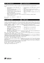
 2.4.1  Descrizione dei DIP-switch

ON

OFF

1

Sensibilità PIR 
alta

Sensibilità PIR 
bassa 

(default)

2

Antimask IR attivo Antimask IR non 

attivo 

(default)

3

PIR in OR

PIR in AND 

(default)

4

Supervisione ON

Supervisione OFF 

(default)

5

CWS ON

CWS OFF

(default)

6

(se 5 è ON)

CWS direzione 
opposta freccia 
scheda

 (par.2.4.6)

CWS direzione 
freccia scheda 
(par.2.4.6)

(default)

NOTA

:  

per ogni cambiamento dei DIP-switch così

come per la variazione del MW Trimmer togliere la
batteria per almeno 10 s e reinserirla per rendere
attive le variazioni.

 2.4.2  Supervisione

Questa   funzione   è   utile   per   aumentare   il   livello   di
sicurezza dell’impianto. I rilevatori con tale funzione
attivata,   DIP-switch     4     ON   inviano   ad   intervalli
regolari un breve 

segnale di esistenza in

vita   alla   ricevente.   E’   necessario   attivare   tale
funzione anche sulla ricevente. 

 2.4.3  Inibizione

Nel   funzionamento   normale   il   rilevatore   attiva
automaticamente   la   funzione   INIBIZIONE   per
risparmiare   la   batteria;   questo   comporta   che   se
l'ambiente è frequentato, il rilevatore rimarrà inibito
fino a quando non trascorreranno almeno tre minuti di
quiete   (nessuna   rivelazione).   Questa   funzione   evita
che   il   rilevatore   trasmetta   di   continuo   situazioni   di
allarme ad ogni passaggio di persone.

NOTA

: per verificare il funzionamento del rivelatore

quindi occorrerà attende almeno tre minuti senza che
alcune persona venga rilevata.

2.4. Detector set-up

Please use this paragraph procedure  to set-up correctly  the
detector.

 2.4.1  DIP-switches configuration


ON

OFF

1

High PIR sensibility Low PIR   sensibility

(default)

2

Antimask IR enabled Antimask


IR

disabled 

(default)

3

OR of the PIR

AND of the PIR 

(default)

4

Supervision ON

Supervision OFF 

(default)

5

CWS ON

CWS OFF 

(default)

6

(if 5 is ON)

CWS   following   the
backwards


arrow

(par.2.4.6)

CWS   following   the
downwards


arrow

(par.2.4.6)


(default)

NOTE

:  

changing   the   DIP-switches   or   MW   Trimmer

position when the detector is powered, the circuit does not
notice it. By removing the battery (at least for 10 s) and
reinsert it the new positions will be read.
 

 2.4.2  Supervision

This   function   is   useful   to   increase   the   safety   level   of   the
installation. Detectors with this feature enabled, DIP-switch 4
ON, at regular intervals send a short

 signal of working

life to the receiver. It is needed to activate that function on
the receiver.

 2.4.3  Stand-by mode

During the normal work the detector enters stand-by mode
automatically   to   save   battery   charge.   During   this   time   the
detector   does   not   transmit   any   possible   alarm   until   the
covered area is clear for at least three minutes.

NOTE

: to check that the detector works correctly, it needs to

wait al least three minutes without detection (no movements
for three minutes at least).

10/12

ON      DIP

 1  2   3  4  5  6

-
+

Summary of Contents for 8017-ISR013

Page 1: ...______________________________________ __MANUALE DI INSTALLAZIONE __ __TECHNICAL MANUAL__ _________MADE IN ITALY________ Rilevatore radio a tenda Wireless curtain detector Art Item 8017 ISR013 8018 IS...

Page 2: ...mazioni riportate in questo manuale sono state compilate con cura tuttavia Italiana Sensori non pu essere ritenuta responsabile per eventuali errori e o omissioni Italiana Sensori si riserva il diritt...

Page 3: ...diretta del sole Evitare la riflessione dell energia elettromagnetica su ampie superfici quali ad esempio specchi pareti metalliche etc Evitare di puntare il sensore su lampade fluorescenti o comunque...

Page 4: ...ppo copri LED LED cap cover KIT tasselli e viti Plugs and screws KIT Manuale di istruzioni Technical manual DIP Switch MW Trimmer LEDs Verde1 Green1 PIR1 Verde2 Green2 PIR2 Giallo Yellow Microonda Mic...

Page 5: ...te a tamper alarm Installazione porta Door installation Installazione finestra Window installation Funzione avanzate Enhanced features Lente coperta da un oggetto Lens covered by object Tentativo di m...

Page 6: ...Trimmer 1 6 Determining the detection area and antitampering accelerometer Covered area it must be determined by applying the following procedure NOTE The detector is developed for cross walking detec...

Page 7: ...i non autorizzate Tale dispositivo non disattivabile e genera un allarme antisabotaggio Area di copertura Window door width The maximum detector coverage width ref pag 6 figure installation A is funct...

Page 8: ...hapter procedure to install correctly the detector 2 1 Detector mounting A Drill two holes in the wall as shown in the figure B Insert the provided plugs in the holes C Fix the detector support using...

Page 9: ...te le prove di rilevazione e copertura radio il rivelatore pronto per il funzionamento NOTA per ogni allarme di antisabotaggio tamper la funzione di test viene ripristinata questo tipo di azione pu es...

Page 10: ...ni passaggio di persone NOTA per verificare il funzionamento del rivelatore quindi occorrer attende almeno tre minuti senza che alcune persona venga rilevata 2 4 Detector set up Please use this paragr...

Page 11: ...ai seguenti DIP switch vedi par 2 4 1 per descrizione DIP switch 5 ON assieme ad una delle seguenti configurazioni Attraversamento secondo il verso della freccia disegnata sul circuito vedi figura in...

Page 12: ...arbonato resistente UV Frequenza radio 868 MHz 2 4 7 PIR sensibility To lower the PIR sensibility if it needs to install the detector in a hostile environment i e outdoor environment direct sunlight e...

Reviews: