background image

Instruction 
Handbook for:

use

adjustment
maintenance

installation

TIME SOLAR

35 K

18 K


IMPORTANT! Install the gasket

 in-

cluded in the documents bag, on 

the  inlet/outlet  flange, 

as shown 

on page 27

.

Summary of Contents for 18 K

Page 1: ...Instruction Handbook for use adjustment maintenance installation TIME SOLAR 35 K 18 K IMPORTANT Install the gasket in cluded in the documents bag on the inlet outlet flange as shown on page 27 ...

Page 2: ...otection against freezing 19 Warnings for the installation of optional kits or special systems 20 Floor heating system 20 Moving the boiler 20 Siphon overflow drain 22 Positioning and fastening 22 Hydraulic system DHW and heating 23 Advices and suggestions to avoid vibrations and noises in the system 23 Cleaning and preservation of the systems 23 Heating system 24 Condense drain 24 DHW storage tan...

Page 3: ...xtra contractual responsibility for any damage arising from wrong installation wrong use and non observance of current laws and instructions given by the manufacturer himself f f Important this gas boiler is used to heat the water at a temperature lower than the boiling one at atmospheric pressure it must be connected to an heating system and or to a domestic hot water system in accordance with it...

Page 4: ... takes place Personnel in charge of installation Place here all necessary advices according to national rules about WORK SAFETY of Personnel in charge of installation An example follows Law number 192 of 19 August 2005 and further revisions Title of the law or brief description Always proceed with caution when handling the boiler and carrying out installation mainte nance work as metal parts may c...

Page 5: ...Methane or Com mercial Propane G31 A qualified technician can convert it to operate with one of these two types of gas above said It must never be used with butane gas G30 that can be present pure or mixed with Propane G31 in the portable gas bottles for cookers except model 18 K The User must not touch sealed items nor break the seals Only specialized technicians and the official technical servic...

Page 6: ...tarting up maintenance and servicing All operations for installation first starting up maintenance servicing and gas conversion must be car ried out by qualified technicians in accordance with the Norms and Laws in force Maintenance operations must be carried out in compliance with the manufacturer prescriptions and in compliance with the laws and rules presently in force for what is not mentioned...

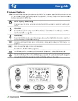
Page 7: ...If the Outdoor Sensor Kit was installed see also Out door Sensor Kit on page 59 DHW setting To set the DHW temperature in the storage below which the boiler intervenes when the solar contribution is too little or lacking It displays all the additional boiler information For deeper details go to INFO menu on page 13 Press to reset the boiler in case of breakdown See Alarms boiler block on page 44 I...

Page 8: ... with solar integration as standard When the boiler is providing heating to the solar storage the symbol blinks Burner ON DHW storage quick heating It indicates that the DHW storage quick heating function is ON It flashes when the boiler is working for that DHW storage heating It indicates that the DHW storage heating is enabled It flashes to inform that the heating of the DHW storage is in proces...

Page 9: ...details rely on kit instruction and see Outdoor Sensor Kit on page 59 Commands outside the boiler Externally the boiler located near to it or suitably positioned in the building generally by the installer or by the electrician two devices that the user should access to are present The presence and the characteristics of these devices are prescribed by the regulation in force Gas cock It is located...

Page 10: ...se of contemporary demand of both DHW storage heating and CH the DHW demand has the priority till the storage gets heated Usually as DHW storage heating does not last for long this priority does not affect the CH efficiency in the system Temperature adjustment Note correct adjustment leads to creating the conditions for energy saving Note if a Low Temperature Kit or an Outdoor Probe Kit are instal...

Page 11: ...he boiler in OFF mode f f the clock hours will be flashing thanks to buttons and is possible to set the hour time f f press the button and the minutes digit will be flashing Therefore adjust the minutes by using the buttons and f f press the button and the weekly day will be flashing Therefore adjust the days by using the buttons and Note for instance in order to set Monday like first weekly day n...

Page 12: ...zable program on a new boiler it s factory set same as program 1 f f The boiler must be set in winter or summer mode no OFF or heating only mode and press the button for at least 5 seconds the display shows the current program number P1 P2 P3 on the right f f choose the suitable program by buttons and and press to load it choosing P3 custom program the relevant data appear on the display now it s ...

Page 13: ...m the copy of the day 1 on the day 2 and skip to this lat ter similarly to copy the program to the further day 3 after and so on it s sufficient to press the button for 5 seconds and press to confirm the copy 11 press the button for at least 5 seconds to exit and return in winter or summer mode as at the beginning INFO menu It is possible to get a few information displayed on the screen as far as ...

Page 14: ...s 9 it means that the outdoor temperature is 9 C below 0 or even lower f f Press the button the display shows the page information which are referred to the solar indicator number 1 flow temperature of the fluid from the solar panel indicator number 2 functional code technical information indicator number 3 temperature of the solar storage upper sensor indicator number 4 temperature of the solar s...

Page 15: ...not mentioned in this User Guide section and expressly allowed to the User Always address yourselves to qualified personnel Boilers must be always equipped with original accessories only ITALTHERM Srl is not responsible for damages caused by the incorrect wrong or unreasonable use of not original materials The burner doesn t turn on f f if the room thermostat or programmable room thermostat or sim...

Page 16: ...boiler s DHW storage Remark the boiler is equipped with a system which protects the main components from the excep tional cases of mechanical lock due to the inactivity in presence of water and scale The anti locking function can t work in Safety shut off mode because of the lack of electrical supply Before re igniting the boiler have a technician check that the pump is not blocked due to inac tiv...

Page 17: ... not protect the sanitary circuit outside the boiler and especially in areas where the heating system doesn t reach For this reason we recommend that you empty the cold and hot sanitary system if they were at risk of freezing Installation Law and regulation prescriptions for the installer Note for the translator writer Place in this paragraph all the recommendations relevant to the compli ance wit...

Page 18: ...nection on the boiler on the wall through gas cock with swivel nut supplied in the fitting kit RI DHW recycle return optional C DHW outlet F Domestic water inlet MS Flow to solar collector system RS Return from solar collector system L Indicative position for electrical power supply wirings SC Indicative position for the condensate drain front view upper view left side view front side front side P...

Page 19: ...2 The minimum pressure limit is foreseen to allow the correct restore of the pressure in the heating system In case of water pressure above the maximum limit it is indispensable to install a PRESSURE REDUCER upstream the boiler The cleaning frequency of the storage coil depends on the water supply hardness If the water hard ness is more than 25 fr it s required to install a softener to bring the h...

Page 20: ...t the antifreeze product added in the heating system Warnings for the installation of optional kits or special systems Floor heating system The safety thermostat s that protects the floor against overheating that could damage the cladding the structure or the system itself must be installed on the flow starting end of the serpentine embedded in the floor itself It should not installed on the syste...

Page 21: ... screws 5 and and remove the panel 6 upwards then unscrew the screws 7 and and remove the panel 8 upwards 00207 C 00 9 d Remove the boiler from the pallet and screw the adjustable screw pads 9 in the positions shown in picture e Place the boiler on the floor and install the panels by carrying out backwards the previous operations ...

Page 22: ...ng and fastening Remark A re usable metal jig D in the figure can be ordered separately so as to facilitate connections and fixing points positioning when the original connection kit is used If the metal jig and or the original connection kit are not used refer to the paragraph Dimensions and connections on page 18 for the position of the connections directly on the boiler f f Locate the exact pos...

Page 23: ...aning and preservation of the systems The efficiency the reliability and the safety of the boilers as all generic thermal systems and compo nents depend strictly on the features of the water that supply them and on their treatment A proper treatment of the water improves the protection of the systems against corrosions and there fore perforations noise leaks etc and limestone incrustations that dr...

Page 24: ...tap close it Heating system filling and pressuring Once all system connections have been carried out and after having filled the DHW storage tank pro ceed with system filling This operation should be made with care respecting the following steps During this operation the boiler should NOT be electrically supplied If the boiler is supplied an automatic system filling cycle will start If the system ...

Page 25: ... is prepared for operation with commercial Propane G31 we recommend notifying the supplier of the fuel for example by applying the sticker provided with the boiler or included in the G31 conversion kit on the gas tank or in its immediate vicinity so that it is visible to the employee when it is being refilled Using Propane gas G31 it is absolutely necessary to install a pressure reducer upstream t...

Page 26: ...For the general electrical supply of the appliance the bipolar switch should be used The use of adaptors multiple taps and extensions is not allowed If the supply cable must be replaced use one of the following cable types H05VVF or H05 VVH2 F The supply cable replacement must be done by qualified personnel It is mandatory the earth connection in accordance with the rules actually in force To repl...

Page 27: ... slope for all the inlet and outlet ducts in order to f f PREVENT the water or dust or other objects entrance inside the INLET duct In case of coaxial ducts use the special horizontal terminal which is especially built to respect these slopes only for the first tract of the inlet duct f f FACILITATE in the OUTLET duct the flowing back of the condense towards the combustion chamber which is built t...

Page 28: ...tes of users Don t lean the flue pipe into the chimney but stop it before the inner surface of the chimney The axis of the flue pipe must intersect the axis of the chimney or of the flue duct In general situations the evacuation systems of the combustion products must be properly declared suitable from the producer of the same system for wet function ing or must be supplied by the appliance s prod...

Page 29: ...5 Pa Separate system Ø 60 mm original accessories Reduction from Ø80mm to Ø60mm on inlet 0 4 m Reduction from Ø80mm to Ø60mm on outlet 1 7 m Linear section or extension Ø60mm length 0 5m on inlet 0 5 m Linear section or extension Ø60mm length 0 5m on outlet 0 5 m Linear section or extension Ø60mm length 1m on inlet 0 9 m Linear section or extension Ø60mm length 1m on outlet 1 m Linear section or e...

Page 30: ...dered IMPORTANT this table is referred to the original flue ac cessories Using non original flue accessories certified for condensation whose use is allowed by the boiler s C6 type certification refer to paragraph Dimensioning the inlet and outlet ducts on page 29 Coaxial system C13 C33 Mod Original coaxial system Ø60 100 mm LCO min max m LCV min max m 18 K 1 8 1 10 35 K 1 8 1 10 00047 00 1300 LCV...

Page 31: ...s of the inlet ducts for their all length or at least only for the external tract is sufficient to prevent that the rain water reaches the combustion chamber 5 so the inlet must not be downwards 6 do not let the condense go out from the flue outlet terminal 7 the coaxial inlet outlet duct must be installed so as the flues are upwards and so the condense discharge itself towards the boiler The term...

Page 32: ...yphon trap contains liquid e g checking that liquid exits the condense drain of the boiler Before firing the boiler check that the pump is not blocked due to inactivity unscrew the plug in the centre of the cap to access the rotor shaft and manually rotate it using a screwdriver or other suitable tool During the commissioning of the new boiler it is necessary to run the burner for 30 minutes befor...

Page 33: ...ulated go on in this chapter as described in the paragraph Combustion test and adjustment on page 39 During the first ignition of the brand new boiler it is necessary that burner works for at least 30 minutes before performing combustion checks During this time the fumes of the eventual residual manufacturing materials are produced and they could alter the measured values f f verify the correct fu...

Page 34: ...ndense verify that the combustion is correctly regulated go on in this chapter as described in the paragraph Combustion test and adjustment on page 39 f f verify the correct functioning of the boiler in heating and domestic hot water version f f fill in the foreseen documentation and leave to the user the copy of his competence Access to the inside of the boiler 1 Remove the boiler s front panel s...

Page 35: ...ut forcing ex cessively Combustion group cleaning Switch off the boiler and disconnect it from the electrical supply Be sure that the parts are not hot and eventually wait the time necessary to cool them Because some contacts with the fine dust and acid condense may occur we recommend to wear the proper de vices for the personal protection i e glasses gloves masque Warning do not wash or damage th...

Page 36: ...he primary exchanger coils by a NOT METALLIC brush and remove the residuals again by using the vacuum cleaner f f locate the lower cap 8 of the siphon where you can access from the lower side of the boiler behind the returned connector of the system put a collector for liquids under it Unscrew the cap Let the siphon empty itself Inside the cover a layer of residual could be present max 1 2mm remov...

Page 37: ... boiler power according to the maximum nominal boiler power maximum boiler power is determined by the gas valve regulation See details in Max heating power adjustment on page 40 12 0 1 0 Burner ignition not modulated to allow the combustion check For deeper details see paragraph Combustion test and adjustment on page 39 Value 0 burner at minimum power Value 1 burner at maximum power Note During th...

Page 38: ...mostat only The boiler can manage a secondary room thermostat installed in a zone that must be heated with a different typology compared to the one where the primary room thermostat or the original Remote Control is installed E g it s possible to foresee with suitable hydraulic sys tem solutions to distribute the heating to the various zones a zone with a low temperature heating system e g the pri...

Page 39: ...onnection Remark The sensor placed at the top of the flue probe must be placed as pos sible in the centre of the flow outlet we advise you to insert well the sensor and so to extract it of 3 cm Insert the sensor so that the protection bow of the sensor placed at the top is trans versal the flow must pass through it and directly touch the sensor Generate a heating request by acti vating the room th...

Page 40: ...you will have to adjust the gas input by turning the screw R Q ADJ ATTENTION turn the screw 1 4 1 2 of turn at a time waiting 1 minute for the values measured to stabilize If the CO2 value is HIGHER than allowed turn the screw R Q ADJ CLOCKwise If the CO2 value is LOWER than allowed turn the screw R Q ADJ COUNTERCLOCKwise Remark if you have adjusted the CO2 at the nominal input we advise you to ch...

Page 41: ...er switches to OFF mode The MAX power for the heating system is adjusted now Power input display fan rpm tables G20 INDICATIVE VALUE par 04 HEAT INPUT FAN RPM kW kcal h Time Solar 18 K MIN 1 7 1462 1200 0 3 2 2752 1600 10 4 5 3870 2050 20 6 0 5160 2450 30 7 5 6450 2900 40 9 2 7912 3300 50 10 8 9288 3700 60 12 0 10320 4150 70 14 4 12384 4600 80 16 2 13932 5000 90 MAX 17 8 15308 5400 99 G20 INDICATI...

Page 42: ...s not work properly f f micro switches SW1 SW5 in OFF position and SW6 in ON position Look out in case of PCB replace ment set the micro switch SW6 to ON on the new spare PCB S1 M15 M4 M2 M16 M6 M1 S1 28 27 26 25 24 23 22 21 39 38 7 8 9 10 1 2 3 4 5 6 68 69 70 71 72 73 74 75 SW1 SW6 ON ON SW 1 ON OFF SW 2 SW 3 SW 4 SW 5 SW 6 00093 00 P1 P2 f f the P1 and P2 trimmers position is indifferent anyway ...

Page 43: ... hose 1 on the sealed chamber compensation plug again 7 open the sealed chamber loosen the swivel nut 5 that connects the gas pipe 6 to the mixer assembly 3 8 unscrew the three screws 4 remove the mixer assem bly 3 and replace it with the one supplied in the conver sion kit 9 screw the swivel nut 5 replacing the gasket 10 close the sealed chamber 11 check with the burner on that the pressure upstr...

Page 44: ...e installed on the boiler s cold water inlet connection f f connect a rubber pipe to the terminal of the storage draining tap 3 f f put the other end of the pipe in a suitable drain or sink f f open the draining tap by turning its hand nut counterclockwise f f when the draining is over close the draining tap turn it clockwise Alarms boiler block Following a malfunction the boiler can lockout and s...

Page 45: ... inlet duct leaks in inlet outlet ducts or errors in sizing of ducts ducts length out of the allowed range and or wrong use of the reducer on boiler s outlet Incorrect electrical power supply Ensure that the Live Neutral and Earth connections are correct and efficient and in particular that the Live and Neutral are not swapped see Electrical diagram on page 56 Remark The problem could also be caus...

Page 46: ...ling of the system flow temperature probe Replacement of the system flow temperature probe E09 Periodical Service maintenance Call Service Technician for planned maintenance operations Pushing User can cancel this for 3 times After that the signal remain on display Even with this signal present boiler is still working properly E10 Low system pres sure and SW6 wrong setting Disconnect the electrica...

Page 47: ...E18 Note it is possible to experience this alarm code during the first filling in when the boiler is just installed due to bleeding of air from the system For this reason at the first time the boiler get electrically supplied the number of fillings allowed before showing the error code are 5 and not 3 for the first 24 hours after the installation Remark Consider that the pressure in normal conditi...

Page 48: ... the electric diagram page 56 and check the integrity of the wirings especially the eventual short cable jumpers between two contacts of the same connector on the cabling connections to the electronic board E35 Unexpected flame the control elec tronic has detected the flame on the burner when this one should be off Wait for the boiler automatic reset 5 minutes or reset it manually by using the but...

Page 49: ...ice s Mains electrical power supply out of tolerance limits Detect the fault or anomaly also referring to the technical literature reserved to the service centres E43 Over temperature of water on system return The water that returns to the boiler from the heating system is too hot this may be an effect of a malfunction of the system and any way this can cause a too high temperature of the flue and...

Page 50: ...lay Board and the Main PCB Refer to the electric diagram page 56 and check the integrity of the wirings between the Display Board and the Main PCB Replace the Display Board and the Main PCB E70 Error parameter s 70 99 out of range Check that values of parameters 70 99 are correct The boiler will return to normal work as soon as all the values are correct Particularly check these parameters values ...

Page 51: ...oned in this handbook we advice to perform them at least once a year to maintain the boiler s performance A careful servicing is always a guarantee of safety and energy saving Normally it will be necessary to execute the following operations f f Remove any possible oxidization from burners and electrodes f f Remove the scale from the exchangers f f Cleaning and checking the exchanger the siphon an...

Page 52: ...cation 0694 CM 3400 0694 CM 3400 Class II2H3P II2H3P Type B23 B23P C13 C33 C43 C53 C63 C83 C93 Working temperature range min max C 0 60 0 60 Max heat input kW 17 8 33 0 33 0 Min heat input kW 1 7 3 4 5 0 Max heat output 60 80 C kW 17 1 32 0 32 0 Min heat output 60 80 C kW 1 6 3 2 4 7 Max heat output 30 50 C kW 18 8 34 7 34 7 Min heat output 30 50 C kW 1 8 3 6 5 2 NOX Class 5 5 5 CO at 0 O2 Qn ppm ...

Page 53: ... automatic filling turning ON OFF bar ON a 0 5 OFF a 1 2 0 2 To allow the correct system filling the pressure of the domestic water should be higher than the OFF value Max working pressure bar 3 3 Max system temperature C 85 85 Anti freezing function temperature on off C 5 30 5 30 HOT WATER Storage volume l 200 200 Specific flow rate EN625 l min 22 24 DHW expansion vessel l 11 11 DHW expansion ves...

Page 54: ...nd gas connections see Dimensions and connections on page 18 Flue types lengths and diameters see Flue systems on page 27 Fan head loss Pa 30 130 30 130 GAS SUPPLY PRESSURE Nominal pressure mbar 20 20 37 Inlet pressure min max mbar 17 25 17 25 35 40 Colour of the calibrated plug for sealed chamber compensation Grigio Argento Grey Silver Yellow Brass GAS CONSUMPTION Qmax m h 1 88 3 49 kg h 2 56 Qmi...

Page 55: ...low meter with valves and connections for filling and draining 20 Drain valve solar system 21 Drain valve DHW storage 22 Lower probe DHW storage 23 DHW storage tank 24 Cental probe DHW storage 25 Drain valve heating system 26 DHW expansion vessel 1 27 Gauge 28 Safety valve 3 bar 29 Pump modulating 30 System pressure transducer 31 Automatic Venting Device heating circuit incorporated in the pump 32...

Page 56: ... 48 49 51 52 40 41 53 54 55 56 57 58 59 60 61 62 63 64 65 76 77 78 79 42 43 44 45 21 22 25 24 23 28 27 26 21 22 25 24 23 28 27 26 3 2 1 6 5 4 9 8 7 2 36 34 35 33 37 1 4 5 3 10 70 69 68 71 72 73 74 75 73 74 75 38 39 3 2 1 6 5 4 9 8 7 10 71 70 69 68 72 M8 M7 M12 S1 TF1 M11 M4 30 29 31 34 33 32 37 36 35 30 29 31 34 33 32 37 36 35 39 38 M6 M1 M2 M15 3 4 5 2 1 M22 M16 P1 M17 P2 TF2 M13 M5 27 26 28 24 2...

Page 57: ... 62 Control keyboard 63 Resistor 2 2 kOhm 1 2W 64 Boiler s main board i the contacts of these components are shown in rest cold conditions To be left always connected in this boiler model Abbreviations BK Black BN Brown BU Blue GN Green GY Grey OG Orange RD Red VT Violet WH White YE Yellow COM Common DHW DHW mode NC Normally Closed NO Normally Open HEA Heating mode Optional external devices 71 Con...

Page 58: ...r to be left always inserted in the SV1 connector in the shown position Optional external devices SS Solar collector temperature probe CR Remote control Terminals of the original ITALTHERM remote control device See also page 60 To install open the junction on the wires and connect them to the device terminals eventually extend the cable TA1 Room thermostat Voltage free Contact for Room Thermostat ...

Page 59: ...35 40 45 MAX MIN Low temperature range 20 45 C if available kd 00 kd 05 kd 01 kd 10 kd 15 kd 20 kd 25 kd 30 00177 ENG 00 Practically kd value should be adjusted depending on the estimated efficiency of the building s ther mal insulation Its range is from 01 to 30 use higher values when there is a high thermal dispersion and therefore a less efficient insulation and vice versa Because of the wide b...

Page 60: ...cable length shouldn t exceed 50 m Install the Remote Control at approx 1 5 m over floor in a place suitable for correct sensing of the room tem perature Do not install behind doors curtains near heat sources nor expose to direct sunlight or water sprinkles 1 Cut off electricity from boiler 2 install the device as described in the paragraph 4 of the supplied instruction booklet 3 link the Remote C...

Page 61: ...Green Heating Technology 61 Notes ...

Page 62: ...Green Heating Technology 62 Notes ...

Page 63: ...Green Heating Technology 63 Notes ...

Page 64: ...960000073_00_ENG 06 05 2015 ITALTHERM Srl declines any responsibility for eventual printing and or transcription errors in the present manual In order to constantly improve its products the company has the right to change features and data written in the present manual at any time and without notice www italtherm it UNI EN ISO 9001 2008 ...

Reviews: