Green Heating Technology
58
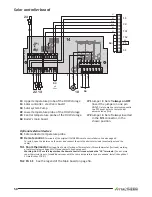
Solar controller board
SS
SE
PA
TA2
TA1
CR
24
JP1
JP2
18
22 13
SV1
RD
VT
VT
WH
WH
GY
GY
GN
GN
BN
BU
YE
-GN
BN
BU
BN
BU
BN
BU
YE
-GN
00240B INT 00
14
64
64
64
M7
40-41
13
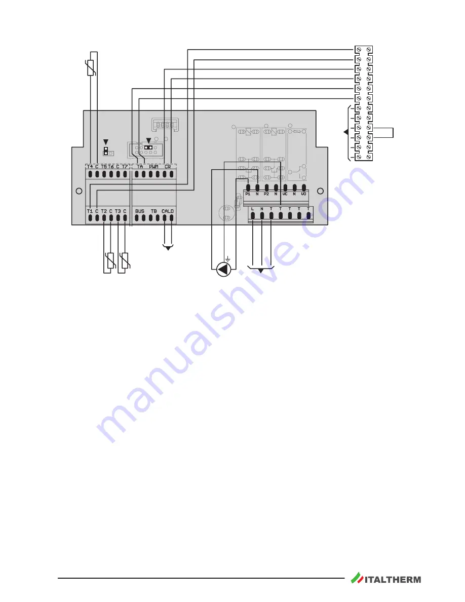
Upper temperature probe of the DHW storage
14
Solar controller - electronic board
18
Solar system Pump
22
Lower temperature probe of the DHW storage
24
Central temperature probe of the DHW storage
64
Boiler's main board
JP1
Jumper to be left
always on OFF
(insert the jumper on one pin
only).
Only to make a reset consequently
to a E31 event (refer to the technical
documentation first)
JP2
Jumper to be left always inserted
in the
SV1
connector, in the
shown position.
Optional external devices:
SS
Solar collector temperature probe
CR Remote control:
Terminals of the original
ITALTHERM
remote control device
. See also
page 60
.
To install
, open the junction on the wires and connect them to the device terminals (eventually, extend the
cable)
TA1 Room thermostat:
Voltage-free Contact for Room Thermostat or Chronothermostat (for trade) working
at safety extra low voltage SELV. Closed contact = heating request.
Warning: Do NOT use this input when the Remote Control is connected on the "CR" terminals.
If one or more
room thermostat inputs, for additional zones with the same temperature type, are needed, install the optional
CH
multi zones PCB kit.
TA2 PA SE
See the legend of the Main board on page 56.


