Green Heating Technology
14
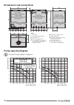
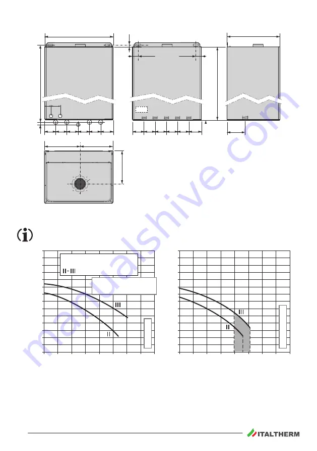
Dimensions and connections
50
45
L
TA
R
M MB G RB
G
R
RB
MB
M
2
400
300
727
9
10
70
70 65 65 65 65
70
70 65 65 65 65
120
23÷43
23÷43
700
TA / L
00382 01
185
207
193
1
Legend:
1
Flue outlet
2
Air intake for coaxial system
M
System flow (¾”)
MB
Flow to storage coil (¾”)
G
Gas: connection on the boiler ¾”;
on the wall, using the optional
original fitting kit ½”
RB
Return from storage coil (¾”)
R
System return (¾”)
TA/L
Indicative position for electrical
power supply and room
thermostat wirings
TA
Room thermostat wiring
L
Electrical power supply wiring
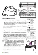
front view -
hydraulic connections
on the wall
(with optional fitting kit)
see also page 17
upper view
front view -
hydraulic connections
on the boiler
left side view -
hydraulic connec-
tions on the boiler
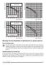
Pump capacity diagram
See also "Pump settings" on page 32.
0
1
2
3
4
5
6
7
0
200 400
1000 1200
600 800
1400
0
1
2
3
4
5
6
7
0
200 400
1000 1200
600 800
1400
00381
A 00
pr
essur
e (m H
2
O)
pr
essur
e (m H
2
O)
water flow (l/h)
water flow (l/h)
speed 3 - 2 of the pump
City Class 20 FR
City Class 25 FR
The graph is referred
to the capacity available
to the system.
DHW s
torage c
oil
CH s
ys
tem


