Green Heating Technology
26
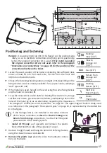
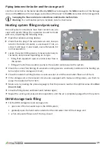
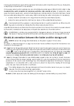
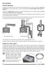
Inlet gas check
Remark:
The pressure should be measured at nomi-
nal input, so this test must be performed with the
burner ignited.
1.
Loosen (2-3 turns) the screw of pressure tapping
point for gas inlet
2
of the gas valve and insert the
manometer sensor;
2.
check that the measured pressure complies with
the inlet gas nominal pressure (see "Technical data"
on page 38).
3.
close the pressure tapping point
2
and
check the
absence of gas leaks
�
Max and Min pressure adjustment
1.
Loosen (2-3 turns) the screw of pressure tapping
point for gas outlet
1
of the gas valve and insert the
manometer sensor. Leave the silicon tube (coming
from the sealed chamber) inserted on the “Vent” 3;
2.
Activate the boiler to its maximum output not mod-
ulated, using the “Chimney-sweeper” function. Proceed as follows:
• the boiler should be electrically powered and set in Heating Only mode. Use the button
if
necessary;
• generate a heating request by activating the room thermostat;
Be sure that the heat produced by the boiler can be eliminated by the heating system (through
the radiators and/or radiant panels/floor systems).
• activate the boiler to its
maximum output not modulated (Qn)
, using the “Chimney-sweeper”
function, that activates by entering the technician menu and setting the parameter
12
to value
1
(see also "PCB parameters settings (technician menu)" on page 27);
3. wait at least 10 seconds
and verify that the measured pressure corresponds to the MAX value
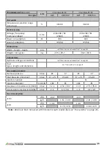
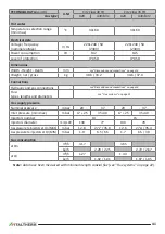
indicated in the Technical data table >
Gas supply pressure
on page 39 or page 41, with regard
to the boiler model and gas type;
4.
extract one of the connectors
4
that supply the modulation coil; verify that the measured pres-
sure corresponds to the MIN value indicated in the Technical data table >
Gas supply pressure
on
page 39 or page 41, with regard to the boiler model and gas type;
5.
reinsert the connector
4
;
6.
if it is necessary to adjust the regulation, proceed as it follows, referring to the figure:
• take off the protection cap
C
;
• adjust MAX pressure acting on the nut
B
(10 mm). Turn clockwise to increase pressure, counter-
clockwise to decrease pressure;
•
extract again one of the connectors
4
;
• adjust MIN pressure acting on the screw
A
(with a 4 mm screwdriver), paying attention not to
contemporarily move the nut
B
. Turn clockwise to increase pressure, counterclockwise to de-
crease pressure;
Pressure tapping points:
1
outlet
2
inlet
3
equalization (VENT)


