23
IN
S
T
A
LLE
R
External Probe Kit
Installation and setting
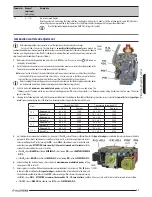
The External Probe automatically manages the system delivery temperature according
to the external temperature, so that the user does not have to adjust it manually. This
function is also defined
"sliding temperature"
.
**
i.e. heating elements temperature. This adjustment does not have to be confused with ambient temperature (settable
on ambient thermostat or on remote control, but not on boiler) which does not depend from the first one.
Installation must be carried out by a qualified technician
following the instructions
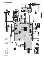
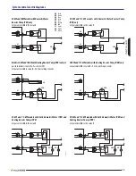
supplied with the kit. For connection to management board see "Boiler electric diagram:"
on page 16.
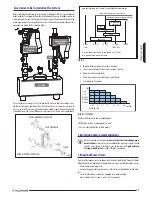
After having installed the external Probe, keys
and
described in the User
Section will not allow setting the delivery temperature any more, but the dispersion
coefficient
"kd"
, e.g. the influence that the external temperature, detected by the
probe, will have on the system delivery temperature, as shown in the following diagram.
35
40
45
50
55
60
65
70
75
78
MAX
MIN
High temperature range 35÷78 °C
–20
t
ext
(°C)
–15
–10
–5
0
5
10
15
20
25 27
20
25
30
35
40
45
MAX
MIN
Low temperature range 20÷45 °C
(if available)
(kd=00)
kd=05
kd=01
kd=10
kd=15
kd=20
kd=25
kd=30
00177
ENG 00
the
kd
value must be adjusted according to the estimated quality of the
property thermal insulation . Its range of adjustment will be from 01 to 30:
the
highest values
are used when there is a
high thermal dispersion
and therefore
a
less efficient insulation
(and vice versa).
Given the great variety of property types, it is not possible to give precise
indications on the
kd
value to set.
a correct adjustment will have to be
evaluated case by case and will result in best comfort in all weather
conditions
which require heating, i.e. a quick achievement of ambient
temperature at cold climate conditions and absence of overheating at mild
climate.
external Probe Kit with optional remote control
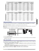
If Remote Control was present, its
P04
parameter (remote ambient modulation type)
must be set on value
2
(modulating on external probe and on-off on ambient probe)
or
3
(modulating on both ambient and external probe) as described in
paragraph 5
of the
booklet supplied with the Remote Control Kit. Therefore, also the
kd
has to be set on this
last one (ref.
paragraph 8 .6
of the same booklet). On the Remote Control, only because
of a display difference, the
kd
range of adjustment will be
0.1...3.0
instead of 01...30.
Remote Control Kit
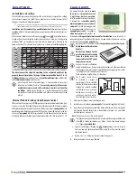
The original Remote Control
is more
than just a chronothermostat:
it optimizes boiler operation
,
interfacing with the relevant electronics.
It incorporates a
complete weekly
climate programmer, easy to be set
and used
: to switch from programmed
to manual operation and vice versa it is
enough to press a key
. It responds to
all boiler controls
and provides the
Technician with
diagnostic information and further functions
. Easy to install, it is
connected in place of the Ambient Thermostat. It is powered by the boiler, in very low
tension and therefore
needs no batteries
.
Remove Remote Control from its box and
keep relevant instructions for use .
attach them to this instruction
booklet .
neither the remote control
nor the relevant cable coming
from the boiler must be
connected to the 230 V power
supply, for no reason .
In order to avoid malfunctions
caused by disturbances, Remote Control connections and other possible low
voltage connections must be kept separated from power supply system cables,
e.g. letting them pass through separate sheaths.
Cable maximum length must be less than 50 m.
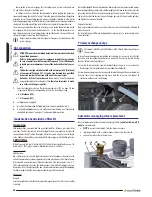
The Remote Control must
be installed at a height of
approximately 1.5 m in a suitable
location for measuring ambient
temperature correctly, avoiding
installation in recess or corners,
behind doors or curtains, and
install away from heat sources,
direct sunlight and water sprays.
1 .
Make sure that boiler is not electrically powered;
2 .
install device as described in
paragraph 4
of the booklet supplied with the Kit;
3 .
connect Remote Control connections to the "Ambient Thermostat - Remote Control"
cable coming from the boiler using a suitable bipolar terminal. See also "Boiler
electric diagram:" on page 16;
Note:
Remote Control connection has no polarity.
Check device correct operation. Electronics automatically recognises it (otherwise
alarm
E31
, already described in par. "Alarms - boiler shut-down" on page
33 is triggered
provided that
:
•
on boiler control panel, through key
,
Summer
mode is always selected.
From now onwards, boiler operation modes (also OFF) will be selected only by
the Remote Control;
•
board is set as in "Settings on electronic board" on page 33.
4 .
the boiler displays the message "
re .on
".
00088a_00
NO
NO
NO
SI
1.5 mt
CON
TRO
LLO
RE
MO
TO
EA
SY
RE
MO
TE
MA
NUA
LE
DI
IST
RUZ
ION
I
Summary of Contents for Time Power 115 K
Page 42: ...42 Notes...
Page 43: ...43 Notes...


