background image

5

U

T

E

N

T

E

US

E

R

Multifunction display

 … 

Day of the week

Displayed: during programming, during standard operation if programming is activated.

00147 A 00

heating - Winter mode

If it flashes, it indicates that the boiler is working in heating mode.

heating request area

It indicates from which area (main "1", secondary "2" or both) heating request comes from.

Domestic water programming time frame

During domestic water programming (see "Setting of the program of boiler no. 3 - User" on page 7) 
it indicates which time frame, between the two available ones, is being programmed

available solar system

 (if connected to the boiler through optional Solar Board)

When boiler is heating solar storage, symbol flashes.

Burner working

Quick boiler preparation

It indicates that the quick boiler preparation function has been activated. It flashes when the boiler is carrying out the quick preparation.

Domestic water - storage heating

It indicates that the boiler is enabled for domestic water heating. If it flashes, it indicates that the boiler is heating.

heating temperature

, in °C (2-digits indicator under the symbol


)

It usually indicates the 

delivery temperature

, i.e. the temperature of the liquid circulating in the heating system, coming out of the boiler.

During heating temperature adjustment (through keys


 and


)

 it displays the set value

.

It is displayed when the boiler is shut down or there is an error which can be reset by the User. See "Alarms - boiler shut-down" on page 33 for error identification 
and for actions to be undertaken according to each different case.
It is displayed when the boiler has a fault or there is an error which can be reset by the Technician. The user can refer to "Alarms - boiler shut-down" on page 33 
for further information and any possible actions to be undertaken according to each different case.

Domestic water temperature

, in °C (2-digits indicator under the symbol


)

It indicates the domestic water storage set temperature.
It indicates that the boiler preparation function is active in a programmed mode.

It indicates, with the symbol  , if at the present moment the boiler preparation function is set to 

ON

 or 

OFF

.

It is displayed when the two digits on its right indicate the boiler operating power. This information is displayed only while menu 

 is used (see "Menu INFO" 

on page 8).
These four digits, in the display lower central area, show different information, e.g. during normal operation: present time, heating system pressure, temperature 
measured by external probe (in this last case, only if the symbol 

 is visible). While menu 

 is used, other data are displayed. For the setting of the dimension 

to normally show, see"4-digits display setting" on page 7; for other relevant information see "Menu INFO" on page 8.
When boiler is electrically powered, but in

 OFF

 mode, this indicator shows the writing

 OFF

.

They show the type of displayed data item on their left. If they are both switched off, the data item is either a time or expressed in a unit of measurement other 
than Bar or °C.
It indicates that the external temperature probe (optional) is connected to the boiler.

Note:

 in this case, system temperature is automatically adjusted and the use of keys 

 and 

 is different: for details refer to the kit documentation 

and to paragraph "External Probe Kit" on page 23.

Boiler external commands

Outside the boiler, conveniently positioned in the property (usually by the installer or 
by the person in charge of installing the electrical system), there are two devices that 
must be used by the user. Their presence and features are prescribed by rules in force:

omnipolar switch: 

it is usually positioned near the boiler and must completely isolate 

the boiler from domestic mains supply. It must be used each time the boiler needs to 
be electrically powered, or when power supply of the equipment has to be switched 
off, e.g. in case of long inactivity periods (see "Safety mode" on page 9) or in 
some alarm cases (see "Alarms - boiler shut-down" on page 33).

ambient thermostat: 

it electrically commands to the boiler the activation or the 

switching off of the heating system, in order to maintain ambient temperature 

(detected by one of its sensors) approximately at a value set by the user. Current 
regulations describe its positioning, temperature limits within which the user can 
adjust it and the switching on and off periods of the heating system. 

Note:

 ITALTHERM offers an advanced chronothermostat, with weekly programming at 

multi-level temperature and other innovative functions. Furthermore, a version with 

radio frequency connection

 and a version with 

GSM command

 are available.

Summary of Contents for Time Power 115 K

Page 1: ...115 K 90 K 70 K 50 K TIME POWER Instruction Handbook for use adjustment maintenance installation ErP 2015 Ready...

Page 2: ...vices kit connection diagram flow balancer and remote boiler heating primary circuit 15 Boiler electric diagram 16 Models 50 kW and 70 kW 16 Models 90 kW and 115 kW 17 Power supply and safeties electr...

Page 3: ...ater treatments are necessary also in case of system filling Forsystemsfunctioningatlowtemperatures watertreatmentmustbecarried outwithachemicalproductforwaterconditioninginthecircuitwithfilming prote...

Page 4: ...installer or an ITALTHERM authorised Servicing Centre SPECIAL RECOMMENDATIONS If you smell gas close gas cock open the window do not use any electrical switches extinguish any flames contact the Servi...

Page 5: ...edwhenthetwodigitsonitsrightindicatetheboileroperatingpower Thisinformationisdisplayedonlywhilemenu isused see MenuINFO on page 8 Thesefourdigits inthedisplaylowercentralarea showdifferentinformation...

Page 6: ...water this last request takes priority for the whole duration of the request itself Since boiler preparation requests have a limited duration in time they usually do not affect room heating Temperatur...

Page 7: ...oload the program with P3 settable program program data are displayed from here it can be modified as showed in Setting of the program of boiler no 3 User on page 7 or load it by pressing for at least...

Page 8: ...ll from one direction or the other f f to quit the menu INFO and go back to standard display press key After 15 minutes switch to standard display is automatic Holiday Menu Note this function can be u...

Page 9: ...er Stand by and anti freeze anti blocking function When boiler is left to OFF for the inactivity period it will be protected from freezing through functions set in the control equipment which heat the...

Page 10: ...ontainment of energy consumptions as implementation of art 4 paragraph 4 of Law No 10 dated January 9th 1991 ATTACHMENT GTO PRESIDENTIAL DECREE No 412 dated August 26th 1993 and Ministerial Decree dat...

Page 11: ...and outer seals of the gas supply system and connections d supply pipe shall have a section equal to or higher than that of boiler e check that the supplied gas corresponds to the gas used for boiler...

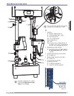
Page 12: ...installation of the eventual safety devices as required by the local national regulation in force and the relevant connection fittings See also Safety devices preset and accessories on page 13 Legend...

Page 13: ...ro bubble separator kit cod 401150003 2 1 Connector for delivery to external boiler always to be used instead of connector 1 11 when this kit is available 3 Insulated horizontal flow balancer kit cod...

Page 14: ...ezza imbuto tronchetto 20 Termostato di blocco sicurezza temperatura impianto termostato limite 21 Pozzetto per la sonda della valvola intercettazione combusti bile 18 22 Pressostato di blocco pressio...

Page 15: ...l shut off valve probe 18 22 Maximum pressure switch 41 Non return valve 42 Zone circulating pump 43 System shut off valve see 44 System filter 45 Boiler see M Thermal module delivery SS Safety valve...

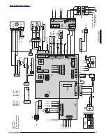
Page 16: ...26 21 22 25 24 23 28 27 26 3 2 1 6 5 4 9 8 7 2 36 34 35 33 37 1 4 5 3 10 70 69 68 71 72 73 74 75 73 74 75 38 39 3 2 1 6 5 4 9 8 7 10 71 70 69 68 72 M8 M7 M12 S1 TF1 M11 44 42 43 45 M9 M4 30 29 31 34 3...

Page 17: ...34 35 33 37 1 4 5 3 10 70 69 68 71 72 73 74 75 73 74 75 38 39 3 2 1 6 5 4 9 8 7 10 71 70 69 68 72 M8 N L M0100 M0101 M0101 M0102 N L M7 M12 S1 TF1 M11 44 42 43 45 M9 M4 30 29 31 34 33 32 37 36 35 30 2...

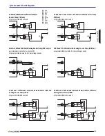
Page 18: ...mark the contact of the minimum pressure switch 82 normally open is shown in rest condition i e at no system pressure In conditions of normal operation the system has the correct pressure and also thi...

Page 19: ...nd 115 kW models with both Domestic Water PRS and HeatingBoosterPumps PRR Set parameter 44 to the value 3 50kWand70kWmodelswithDomesticWater BoosterPump PRS only Set parameter 44 to the value 3 Models...

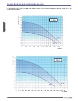
Page 20: ...pump is modulating therefore diagrams show maximum and minimum work limits 0 0 5 1 1 5 2 2 5 3 3 5 4 4 5 5 5 5 6 6 5 7 7 5 8 8 5 0 200 400 1000 1200 600 800 1400 1600 1800 Portata l h Prevalenza m H...

Page 21: ...0 2400 2600 3000 2800 3400 3600 3200 3800 4000 4200 4400 4600 Portata l h Prevalenza m H 2 O MAX MIN 90 K 0 0 5 1 1 5 2 2 5 3 3 5 4 4 5 5 5 5 6 6 5 7 7 5 8 8 5 9 9 5 10 10 5 0 200 400 1000 1200 600 80...

Page 22: ...ulations Have qualified personnel check that the wiring is suitable for the maximum power absorptionoftheequipment asindicatedinthetechnicalplate makingsureinparticular that the diameter of cables is...

Page 23: ...astone ref paragraph8 6ofthesamebooklet OntheRemoteControl onlybecause of a display difference the kd range of adjustment will be 0 1 3 0 instead of 01 30 Remote Control Kit The original Remote Contro...

Page 24: ...thus preventing a complete heat exchange When the electrolyticcorrosionprocessstarts thesystemwaterlevelisreduced gasesaccumulate intheuppersectionoftheheatexchangerandradiators Thepresenceofairiscau...

Page 25: ...t metals or by the presence of chlorides 3 DEPOSITS These are insoluble organic and inorganic substances SLUDGE PROCESSING RESIDUES The water in domestic heating systems should be treated in the follo...

Page 26: ...ot comply but there are no signs of corrosion Install Y filter micro impurity separator micro air bubbles separator adequate filling water chemical physical treatment to reduce hardness and reach a co...

Page 27: ...f 5 10 m that cause the worst problems processing residues hair rust sand lodestone BENEFITS Impurity discharge while the system is working There is no need to install check valves or bypass circuits...

Page 28: ...charcoal inside the first section of the pipe while the second step is to increase the pH value Condensation acidity can be checked with litmus paper used to define pH value Servicing Withreferencetol...

Page 29: ...asurementsarereferredtotheboilerupperprofileandimmediatelytotheentryofthe firstright anglecurveDifferencesinlevelsduetoslopesarenotconsidered IMPORTANT table is referred to original flue fitting acces...

Page 30: ...ient to eliminate any possible residue resulting from previous combustion and therefore facilitate burner adjustment Factory setting is ideal for most cases and it isadvisablenottomodifyit Notethatboi...

Page 31: ...be activated selecting parameter 12 and setting value 0 see Boiler parameter setting technical menu on page 30 burner ignites at low flow 4 referringtothefollowingtable verifythatthenumericalindicato...

Page 32: ...page 30 select parameter 04 and prepare to modify its value Burner ignites 3 referring to Capacity display rotations on page 32 set parameter 04 to the value corresponding to the necessary thermal ca...

Page 33: ...starting phase when power supply is restored In all boilers ofTime Power range setting will have to be the following otherwise boiler will not work correctly S1 M15 M4 M2 M16 M6 M1 S1 28 27 26 25 24 2...

Page 34: ...combustion unit has overheated and the relevant thermostat see page 40 or page 41 has intervened This is a protection forthecombustionunit butitisusuallyanticipatedbytheothersafetythermostats Shouldth...

Page 35: ...ntinues or occurs again call the Assistance Service Recognise any possible malfunctioning of gas valve which does not interrupt gas flow and therefore burner stays on or electronics flame control sect...

Page 36: ...er programming see Setting of the program of boiler no 3 User on page 7 ErP Data EU 813 2013 Supplier name Italtherm Contact details Italtherm Srl Via Salvo D Acquisto 10 29010 Pontenure PC Italy Mode...

Page 37: ...Power 60 80 C kW 4 7 5 6 6 6 6 6 Maximum Thermal Power 30 50 C kW 49 2 49 2 65 6 65 6 Minimum Thermal Power 30 50 C kW 5 2 6 2 7 3 7 3 Class NOX 5 5 5 5 Correct CO 0 O2 at Qn ppm 157 3 146 3 146 0 172...

Page 38: ...pen close mm 100 460 345 740 570 470 GAS CONSUMPTION Qmax m h 5 02 6 66 kg h 3 68 4 88 Qmin m h 0 53 0 74 kg h 0 47 0 62 TECHNICAL SPECIFICATIONS Unit of measurement Time Power 90 K Time Power 115 K R...

Page 39: ...by the installer Maximum working pressure bar 4 5 Boiler water content l 9 11 5 Max temperature C 95 Boiler anti freeze function temperature on off C 5 30 DOMESTIC WATER DATA Temperature selection ra...

Page 40: ...ion unit air purging manual valve 6 Fume thermal fuse 7 Ignition electrode 8 Suction hose 9 Discharge igniter 10 Mixer air gas mixing device 11 Motor driven fan 12 System return temperature probe 13 G...

Page 41: ...Boiler safety thermostat delivery 7 System return temperature probe 8 System delivery temperature probe 9 Combustion unit thermal fuse non replaceable 10 Ignition electrode 11 Modulating circulation...

Page 42: ...42 Notes...

Page 43: ...43 Notes...

Page 44: ...960000084_05_ENG 20170202 ITALTHERM Srl declines any responsibility for eventual printing and or transcription errors in the present manual In order to constantly improve its products the company has...

Reviews: