0
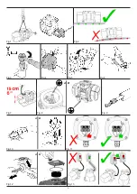
- Unscrew the mobile weight screw fastener or nut (Fig. 19, page 7). The
adjustable weights positioned at the two ends of the shaft must be positioned
in a way to read the same value on the reference percentage scale. The
weights positioned at the two sides of the vibrator can only be adjusted
on two different values for particular machines and for special uses.
- Once the eccentric weight has been taken to the desired value tighten the
screw fastener or nut using the dynamometric wrench (Fig. 20 page 7)
and repeat the same operation on the opposite weight (see the table on
page 85 for coupling torques)
- Once the operation on the two sides has been carried out, remount the
covers on the screws and washers paying attention that the seals are
correctly positioned in their houses (Fig. 21, page 7)..
4.2 START-UP AND SHUTDOWN OF THE VIBRATOR
DURING USE
Start-up takes place by always and only acting on the power supply switch by
positioning it in the ON position (insertion of the power supply network).
The vibrator works.
Stop the vibrator by always and only acting on the power supply switch
by positioning it in the OFF position (disconnection of the power supply
network).
SECTION 5 –
Maintenance of the vibrator
ITALVIBRAS vibrators have no particular need for maintenance.
Maintenance, repair and overhaul operations have to be carried out
in compliance with the instructions of this manual and in compliance
with the standards and laws in force in the country of use, for the
specific zone of use, with specific reference to potentially explosive
atmospheres.
The CDX-IMX-VMX explosion-proof electric vibrators are in protection
mode “d” and they have flame joints subjected to accurate preliminary
checks before manufacturing.
In case of maintenance, repair and overhaul, always check the complian-
ce of the flame joints with the requirements. For the joints tolerances
see fig.28 page 91.
In order to respect the belonging category it is necessary to assure the
respect of the mechanical protection IP66 of the enclosure.
Every time a maintenance, repair or overhaul operation is carried out
on a the vibrator, is necessary to check the seals conditions and the
correct placement in the seats.
Only authorized technicians can intervene on the parts that make up
the vibrator.
Before carrying out maintenance on the vibrator wait until the tem-
perature of the vibrator case is not above 40°C and ensure that the
electrical power supply has been disconnected.
If parts must be replaced, only ITALVIBRAS original spare parts must
be used.
All maintenance, repair and overhaul operations carried out by a third
part and not by ITALVIBRAS void warranty.
5.0 ADMITTED AND NOT ADMITTED OPERATIONS
BY USER
The CDX-IMX-VMX electric vibrators are intended to be used in potentially
explosive atmospheres and the safe operation in these environments
is assured by the protection mode of these vibrators and so by the
components and by assembling system. Therefore the admitted works
ENGLISH
ENGLISH
by user for repairs, overhauls and maintenance are strictly limited.
The only admitted operations of maintenance for the user are the
followings:
- cleaning of the external surface of the electric vibrator, eliminating
dust and dirty in excess;
- periodical lubrication of the electric vibrator, following instructions
in paragraph 5.1;
- replacing of the terminal box cover, of the weight covers and relative
seals, only with original Italvibras spare parts.
Maintenance and repairs involving disassembling of other parts of the
electric vibrator are NOT admitted.
The only parts that can be disassembled are:
- terminal box cover only to complete the electrical connection of the
electric vibrator with the supply line;
- weight cover to adjust and replace eccentric weights and to check
the direction of rotation.
In case it is necessary to disassemble other parts not mentioned above
it’s necessary to apply to Italvibras - Fiorano Modenese (Italy).
Among these forbidden operations are included also the replacement
of the bearings, of the wound stator and of other internal parts.
In order to assure the belonging category of the electric vibrator the
bearings condition is essential.
Consequently the bearings have to be maintained in good condition
and, in case of anomalous noise, the bearings have to be replaced.
In case of problems always contact Italvibras - Fiorano Modenese
(Italy).
ATTENTION: Every time the aforementioned maintenance operations
are carried out it is recommended that all
disassembled screws and spring washers are replaced and that the
screws are tightened using a dynamometric wrench.
5.1 LUBRICATION
All bearings are correctly lubricated on mounting the vibrator.
Therefore when the electric vibrator is supplied, the user DON’T have
to lubricate the bearings.
During operation
the user can choose between two possible alternati-
ves:
- do not relubricate (FOR-LIFE system): choice advisable only in presence
of low duty conditions or in cases where the re-lubrication is impossible,
too expensive or unreliable;
- relubricate through the two lubrication channels provided, according to the
following indications (Fig. 22 page 8):
ATTENTION: This operation must be carried out strictly by specialized
personnel and with the power supply disconnected.
- disconnect the power supply to the vibrator and wait for the vibrating
machine to stop;
- unscrew the 2 caps that protect the entrance to the lubrication channels
and keep them aside;
- screw in 2 suitable grease nipples (1/8 ”NPT thread) and pump the required
quantity of grease;
- unscrew the 2 grease nipples and screw the 2 caps back on, restoring the
original condition.
WARNING: It is essential that during operation the lubrication channels
are closed with the plugs screwed down as original supply. Failure
to comply with this condition can lead to danger in the event of an
explosion.
Summary of Contents for CDX IMX VMX Series
Page 4: ...1 2 4 5 D B C A 3 D 1 2 5 CDX G 4 35 40 50 CDX G D 3 35 40 50 60 70 80...
Page 6: ...Fig 1 Fig 2 Fig 3 Fig 4 Fig 5 Fig 6 Fig 7 Fig 8 A B Fig 10 Fig 11 A B A B Fig 12 Fig 13 Fig 9...
Page 7: ...Fig 14 A C B Fig 15 Fig 16 Fig 17 Fig 18 Fig 19 Fig 20 Fig 21...
Page 8: ...NOTE Fig 22...
Page 9: ...NOTE...
Page 82: ...82...

