background image

4

v081118

  5

FRANÇAIS

ENGLISH

ENGLISH

FRANÇAIS

4

v081118

  5

FRANÇAIS

ENGLISH

ENGLISH

FRANÇAIS

OPERATING INSTRUCTIONS

A

B

C

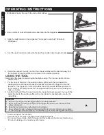
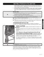
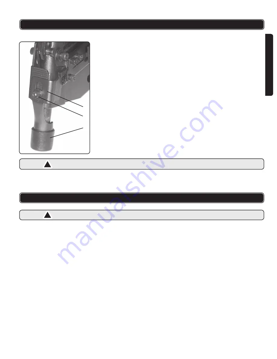
FASTENER DEPTH

The depth to which a fastener is driven is controlled by the depth adjustment (A). The 

depth drive is adjusted to the maximum setting by the factory. 

TO ADJUST

1.  Loosen Screw (B), slide the adjustment to the desired position and retighten the 

locking screw.

NOTE:


 

Sliding the safety bracket (A) upward increases the depth of the drive.

 

Sliding the safety bracket (A) down decreases the depth of the drive.

2.  Test fire another fastener in a scrap work piece and check the depth. 

REPEAT 

AS NECESSARY UNTIL DESIRED DEPTH IS ACHIEVED.

 The amount of air 

pressure required will vary depending on the size of the setting. To determine the 

lowest setting that will consistently perform the job at hand. Air pressure in excess 

of that required can cause premature wear and/or damage to the tool.

3.  A rubber nose cushion (C), is provided to reduce marring of the work surface. The 

rubber cushion can be removed to increase the depth of the drive.

CAUTION: 

Disconnect tool from the air supply before removing or installing the rubber 

cushion.

Don’t use the tool without nails in the magazine. When there are only two or three nails left 

in the magazine, the tool may misfire. It is not necessary to take the nails out. Simply place 

a new strip of nails in the magazine and operate normally.

MAINTENANCE

CLEARING A JAMMED FASTENER

1.

  CAUTION: 

disconnect the tool from the air supply.

2.  Remove any remaining fasteners from the nailer.

a.  Pull feeder all the way to the rear until it latches

b.  Slide the fasteners to the rear, and remove fasteners from the magazine

3.  Use a pair of needle nose pliers and/or a flat screwdriver to remove bent fasteners 

from the back of the nosepiece.  If fastener cannot be removed as described, it may be 

necessary to disassemble the magazine as follows:

a.  Remove three screws (68 & 65) on the left front of the magazine and remove 

screws 35 on the right front.

b.  Remove support (73)

c.  Slide the magazine back, off the nosepiece.

d.  After clearing bent fastener, reassemble in reverse order.

REGULAR MAINTENANCE

 

Clean and inspect the tool daily. Make sure the tool is disconnected from the air supply.

 

Blow the tool clean with compressed air and inspect for wear or damage. Use non-

flammable cleaning solutions to wipe the exterior of the tool only if necessary. DO NOT 

SOAK tool with cleaning solutions. Such solutions can damage internal parts.

 

Inspect the trigger and the safety mechanism to assure the system is complete and 

functional. Check for loose or missing parts, and any parts that may be sticking.

 

Keep all the screws tight. Loose screws may cause personal injury.

 

Place two or three drops of pneumatic oil (included) into the air inlet of the tool daily.

!

!

Summary of Contents for FN2890

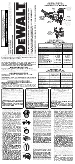
Page 1: ...e for future reference CONSERVEZ CE GUIDE Vous aurez besoin de ce guide pour les instructions de sécurité les procédures d utilisation et la garantie Conservez le dans un endroit sûr et sec pour référence future PROD NO 013136 MOD NO FN2890 v 081118 28o 30o Framing Nailer Operator s Manual p 2 Cloueuse de charpenterie 28o et 30o Manuel de l utilisateur p 8 ...

Page 2: ...ns for the free movement of trigger and safety mechanism 11 REPLACEMENT PARTS When servicing use only identical ITC replacement parts and fasteners recommended by us 12 CONNECT TOOL TO AIR SUPPLY BEFORE loading fasteners to prevent fasteners from firing during connection The fastener driving mechanism may cycle when the tool is connected to the air supply 13 ALWAYS ASSUME THE TOOL CONTAINS FASTENE...

Page 3: ... is ideal All compressed air contains moisture and other contaminates that are detrimental to internal components of the tool An airline filter will remove most of these contaminates and significantly prolong the life of the tool If an in line oiler is not available place 2 or 3 drops of oil into the tool s air inlet at the beginning of each workday CAUTION All line components hoses connectors fil...

Page 4: ...re method provides the most accurate fastener placement In this method the safety bracket can be adjusted with the knob to avoid striking two nails at one time 2 Another method to firing the gun is bump fire Keep the trigger pressed then push the safety bracket to the working surface Once the bracket is pushed back enough the nail will fire CAUTION Remove your finger from the trigger when not driv...

Page 5: ... the nails out Simply place a new strip of nails in the magazine and operate normally MAINTENANCE CLEARING A JAMMED FASTENER 1 CAUTION disconnect the tool from the air supply 2 Remove any remaining fasteners from the nailer a Pull feeder all the way to the rear until it latches b Slide the fasteners to the rear and remove fasteners from the magazine 3 Use a pair of needle nose pliers and or a flat...

Page 6: ...rability standards and are warranted for two years against manufacturers faults and defects for a period of two years from the date of purchase to the original owner ITC will REPAIR OR REPLACE at our discretion merchandise deemed by the company to be defective provided that it is has not been misused abused altered or repaired by anyone other than an authorized repair centre Please consult the ITC...

Page 7: ...ew M8 x 25 33 Spring 34 Safety bracket A 35 Screw M5 x 12 36 Bushing 37 Safety bracket B 38 Washer 39 Screw M5 x 10 40 Rubber cover 41 Seal 42 Pin ITEM DESCRIPTION 43 Safety bracket guide 44 O Ring 20 3 x 2 5 45 O Ring 20 3 x 1 5 46 Valve set 47 O Ring 9 5 x 1 9 48 O Ring 10 3 x 1 9 49 Trigger valve head 50 O Ring 12 8 x 1 9 51 Spring 52 O Ring 5 5 x 1 5 53 Trigger valve stem 54 O Ring 24 8 x 2 55...

Page 8: ...èces qui a des pièces endommagées ou qui doit être réparé Assurez vous que toutes les vis et les chapeaux sont bien serrés 10 VÉRIFIEZ S IL Y A DES PIÈCES ENDOMMAGÉES N utilisez jamais l outil si le dispositif de sécurité le déclencheur ou le ressort ne fonctionnement pas de manière appropriée s ils manquent ou s ils sont endommagés Ne modifiez pas et ne retirez pas le dispositif de sécurité le dé...

Page 9: ... ainsi qu à toutes les autres instructions de ce guide Conservez ce guide et assurez vous qu il est disponible pour tous les utilisateurs de cet outil Pour la sécurité personnelle et le bon usage de cet outil lisez et suivez toutes les directives attentivement INSTRUCTIONS D UTILISATION Le modèle FN2890 de ITC est une cloueuse de charpenterie pneumatique de service intense avec un corps léger de m...

Page 10: ... avant de charger les clous dans l outil Ne chargez pas les clous quand le déclencheur ou le dispositif de sécurité sont en foncés Portez toujours des lunettes de protection et une protection des oreilles approuvées en préparant et en utilisant cet outil 2 Tirez le sabot complètement vers l arrière jusqu à ce qu il se bloque 3 Alignez une bande de clous avec les pointes vers la bas et placez la da...

Page 11: ...r à laquelle le clou peut être enfoncé est contrôlée par le réglage de profondeur A Le réglage de profondeur est ajusté à la profondeur maximum à l usine Pour ajuster 1 Desserrez la vis B ajustez le réglage à la position désirée et resserrez la vis REMARQUES Remonter le dispositif de sécurité A augmente la profondeur à laquelle le clou est enfoncé Abaisser le dispositif de sécurité A diminue la pr...

Page 12: ...internes Inspectez le déclencheur et le mécanisme de sécurité pour vous assurer de l intégrité et du bon fonctionnement du système Vérifiez qu aucune pièce n est lâche manquante ou coincée Assurez vous que toutes les vis sont bien serrées Des vis desserrées peuvent entraîner des blessures Mettez deux ou trois gouttes d huile pneumatique comprise dans la prise d air de la cloueuse à chaque jour CAU...

Page 13: ... REMPLACÉS au gré de ITC La présente garantie ne s applique cependant pas aux défectuosités découlant d un usage impropre ou abusif d une usure anormale ou de modifications effectuées hors de l usine S V P consulter le catalogue pour obtenir la liste des produits qui font partie de la garantie échange au comptoir Lorsque le produit est admis à la garantie au comptoir il doit être retourné au point...

Page 14: ...s M5 x 12 36 Douille 37 Dispositif de sécurité B 38 Rondelle 39 Vis M5 x 10 40 Coussinet en caoutchouc 41 Anneau en caoutchouc 42 Goupille No DESCRIPTION 43 Plaque de guidage 44 Joint torique 20 3 x 2 5 45 Joint torique 20 3 x 1 5 46 Ensemble de soupape 47 Joint torique 9 5 x 1 9 48 Joint torique 10 3 x 1 9 49 Tête de soupape du déclencheur 50 Joint torique 12 8 x 1 9 51 Ressort 52 Joint torique 5...

Page 15: ...v081118 15 FRANÇAIS ENGLISH v081118 15 FRANÇAIS ENGLISH SCHEMATIC DRAWING SCHÉMA ...

Reviews: