background image

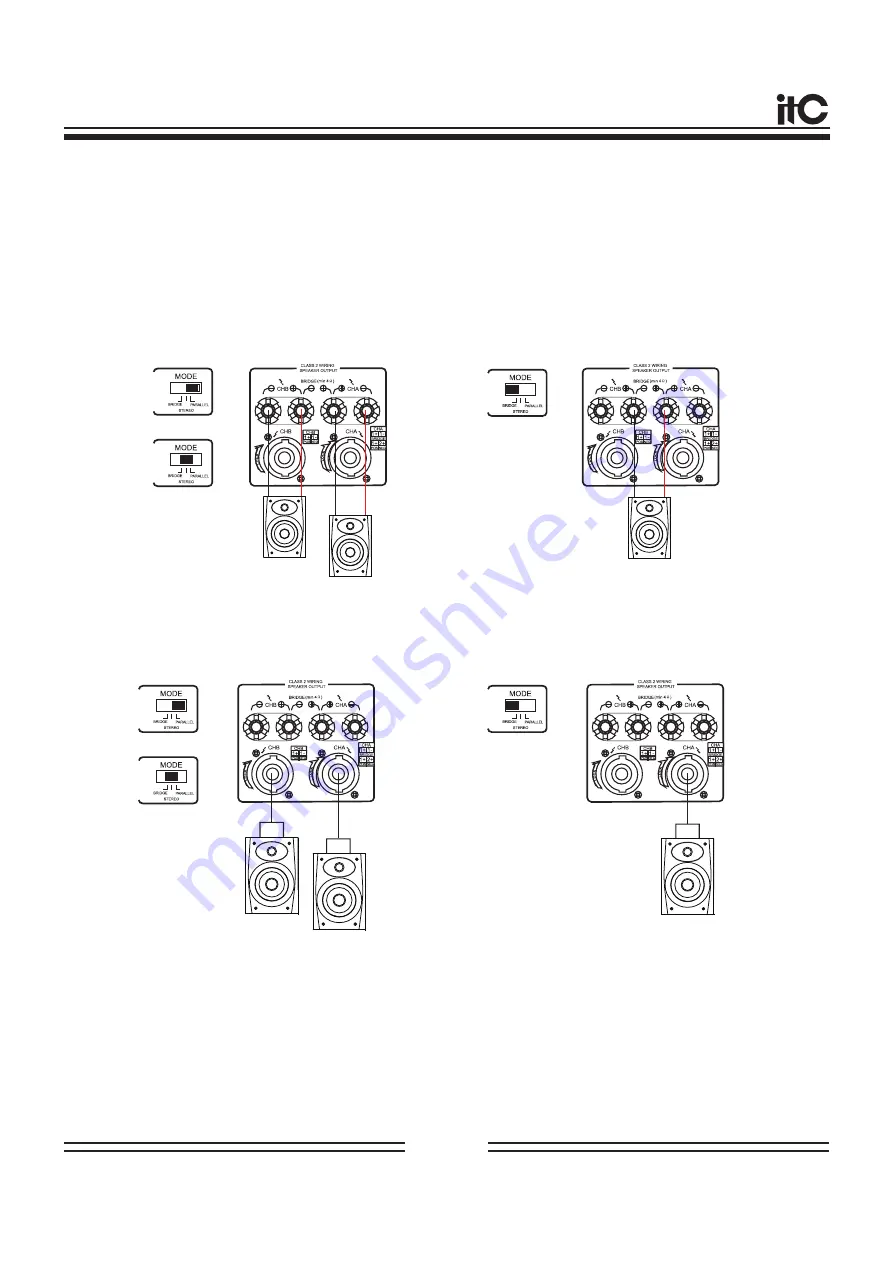
T H E  C O N N E C T I O N  O F T H E  S P E A K E R

The impedance of the speaker:


Connect the speaker as shown below:

Under the STEREO and PARALLEL mode to 

    connect the configuration, when use the binding
    post socket:

Under the BRIDGE mode to connect the 

    configuration, when use the binding post 
    socket:

Under the STEREO and PARALLEL mode to 

    connect the configuration, when use the 
    SPEAKON socket:

Under the BRIDGE mode to connect the 

     configuration, when use the SPEAKON 
     socket:


The Minimum Impedance of the speaker: 2

Ω


The Minimum Impedance of the speaker: 4

Ω

SPK-

SPK+

SPK-

SPK+

SPK-

SPK+

SPK-

SPK+

SPK-

SPK+

SPK+


TO


PIN1

+

SPK

TO


PIN1

-


SPK+


TO


PIN1

+


SPK

TO


PIN1

-

SPK-

SPK+

SPK+


TO


PIN1

+

SPK

TO


PIN2

+


The Minimum Impedance of the speaker: 2

Ω


The Minimum Impedance of the speaker: 4

Ω

Please notice:


The impedance of the speaker changed alone with the connection way and the sets of the speaker. 

Please make sure that the impedance will not lower than the minimum value as shown above.

Page 8 

Summary of Contents for PRECISION Series

Page 1: ...ANUAL PROFESSIONAL POWER AMPLIFIERS PROFESSIONAL POWER AMPLIFIER CHA MIN MAX CHB MIN MAX POW PRO CLP SIG PRO CLP SIG TA 2700 PROFESSIONAL POWER AMPLIFIER CHA MIN MAX CHB MIN MAX POW PRO CLP SIG PRO CLP SIG TA 21200 PROFESSIONAL POWER AMPLIFIER ...

Page 2: ...d rear panel of this equipment to avoid the internal high temperat ure Please do not obstruct these vent holes Otherwise it will cause fire Please note DO NOT Put this device side or upside down Put this device on poorly ventilated places such as built in wardrobe or cupboard bookcase rather than installing on the matched holder Cover this device with tablecloth or put on carpet or in bed Please r...

Page 3: ...put It may cause fire if use other cables Please power off all other instruments audio device and speakers And use the correct cables to connect accordingly Please adjust the volume control to minimum before turning on the power of this device Other wise sudden outbreak of voice may damage your hearing Please do not use this amplifier for any other purpose except driving the speaker Please pull ou...

Page 4: ...ly dimensioned power supplies with low leakage toroidalcore transformers provide considerable head room well above the nominal ratings V I foldback limner circuits were deliberately not included in the PRECISION SERIES power amplifiers to facilitate operation at complex loads up to a phase angle of 90 The inputs are electronically balanced on XLR connectors Isolation transformers can be retrofi tt...

Page 5: ... safely 5 Built in 30Hz 50Hz high pass filter 6 Multiple modes stereo bridge and parallel 7 Plentiful reserve power with 2R low impedance output high fidelity sound which can perfectly restore audio quality to allow the actors to play incisively and vividly 8 High quality low impedance transformer and large capacity electrolytic filter to ensure working in large dynamic range 9 H class efficient p...

Page 6: ...e appears overheating protection of amplifier and transformer the indicator will show red If machine is in protection status for a long time after turning on the machine is faulty please contact your dealer Clipping Indicator When the yellow indicator is lit by signal the output signal has been distorted indicating that the input signal is too large please reduce the input signal Signal Indicator ...

Page 7: ...Protect Indicator When the machine appears overheating protection of amplifier and transformer the indicator will show red If machine is in protection status for a long time after turning on the machine is faulty please contact your dealer Clipping Indicator When the yellow indicator is lit by signal the output signal has been distorted indicating that the input signal is too large please reduce t...

Page 8: ...or connect to the chassis of the mixer preamp or other device Over current protection device Channel A B binding post output jack Channel A voltage limiting switch Channel A high pass filter trigger Working modes selector switch STEREO mode Channel A and Channel B are autonomous working The input signal of channel A will be output by its output jack The input signal of channel B will be output by ...

Page 9: ...f the mixer preamp or other device Over current protection device Channel A B binding post output jack Channel A voltage limiting switch Channel A high pass filter trigger Working modes selector switch STEREO mode Channel A and Channel B are autonomous working The input signal of channel A will be output by its output jack The input signal of channel B will be output by its output jack PARALLEL mo...

Page 10: ...nal Cold End For unbalanced input method PIN 1 and PIN 3 are short circuiting Input sensitivity is 1V OUTPUT INPUT CONNECTION METHODS Input Link Pin 1 and Pin 1 Pin 2 and Pin 2 1 1 1 1 Speakon Cable Speakon 2 conductors Speakon Pin1 connection Please notice To avoid the fan hole of the machine is blocked which caused the machine over heat please tear down the dust screen from the panel on a regula...

Page 11: ...et Under the BRIDGE mode to connect the configuration when use the SPEAKON socket The Minimum Impedance of the speaker 2Ω The Minimum Impedance of the speaker 4Ω SPK SPK SPK SPK SPK SPK SPK SPK SPK SPK SPK TO PIN1 SPK TO PIN1 SPK TO PIN1 SPK TO PIN1 SPK SPK SPK TO PIN1 SPK TO PIN2 The Minimum Impedance of the speaker 2Ω The Minimum Impedance of the speaker 4Ω Please notice The impedance of the spe...

Page 12: ... 2 GND PRIORITY CHIME LED PWR MIC INPUT 1 3 5 6 7 1 3 6 CHIME REMOTE MODEL NO T 2S01 PRE AMPLIFIER 2 OUTPUTS 1 NO 1 AMPLIFIER REC LINE 10 LINE 9 LINE 8 LINE 7 LE FT RI G HT MIC INPUTS MIC LINE INPUTS 220V 50Hz MAX 9 9W P T T 1 2 3 4 5 6 7 8 9 10 INSIDE AC DC FUSE 220VAC DC POWER 24V MAX 0 6A AVIS RISQUE DE CHOC ELECTRICUS NE PAS QUVRIR RISK OF ELECTRIC SHOCK DO NOT OPEN PUBLIC ADDRESS SYSTEM SERIA...

Page 13: ...Rear panel wiring diagram 3U REAR PANEL WIRING DIAGRAM Page 10 SPEAKER SPEAKER AMPLIFIER AMPLIFIER NO 1 NO 2 SPEAKERS SPEAKERS ...

Page 14: ...Hz 200 Size mm 484 530 132 484 490 88 Weight 18 5Kg 27 5Kg 30 5Kg 34Kg Output Power Bridge Connection 4R TA 2500 500W 2 750W 2 1100W 2 1500W TA 2700 700W 2 1050W 2 1550W 2 2100W TA 2900 900W 2 1350W 2 2000W 2 2700W 4000W TA 21200 1200W 2 1800W 2 2700W 2 3600W Stereo Parallel 8R Stereo Parallel 4R Stereo Parallel 2R Bridge Connection 8R 2200W 3100W 5400W TECHNICAL PARAMETERS Page 11 ...

Page 15: ...SIONAL POWER AMPLIFIERS PRECISION SERIES V0 1 This manual Specifications and descriptions are for reference only The Company reserves the right to change products or specifications at any time without notice ...

Reviews: