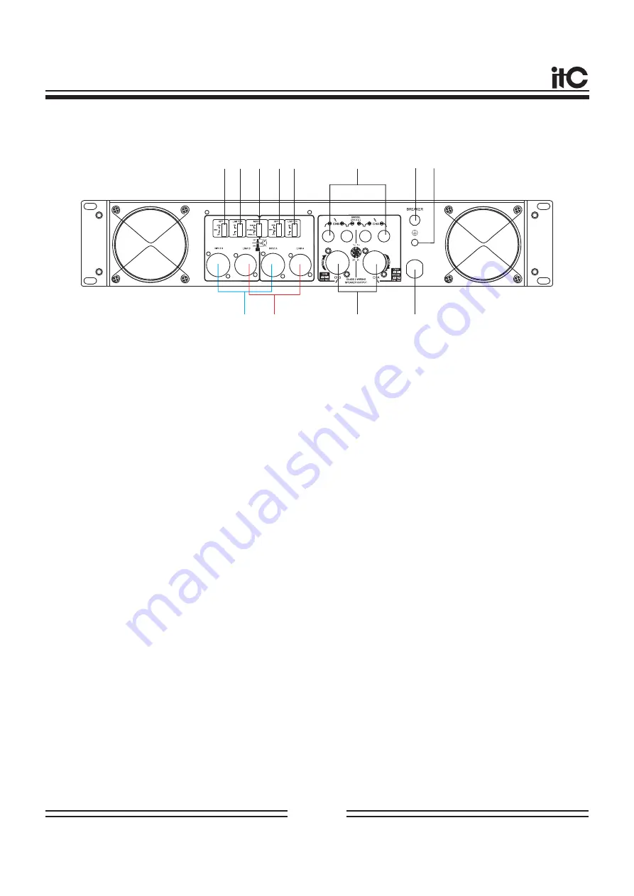
Rear panel(2U):
1
3
4
5
6
7
8
9
10
11
12
2
REAR PANEL FUNCTION
1
.
.
3
.
4.
5
.
6
.
7
.
The output of the loudspeaker is connected between the red and black binding posts of
each channel, while it will be connected between two red binding posts when bridging.
8
.
9
.
10
11.
12
.
Channel A/B balanced and unbalanced input
(Note: When using BRIDGE or PARALLEL mode, only the jack of channel A is effective).
2
Channel A/B balanced LINK output.
Amplifier channel A/B SPEAKER jacks
Neutrik NL4FCSPEAKON is used as an output connection jack.
AC power input
Before connected to main grid, please check if the voltage is consistent with the marked.
GND Terminal
This is a screw-type ground terminal. If you are having a problem with “hum” or noise, please use
this terminal to ground or connect to the chassis of the mixer, preamp, or other device.
Over-current protection device
Channel A/B binding post output jack
Channel A voltage limiting switch
Channel A high-pass filter trigger
.
Working modes selector switch
①
STEREO mode: Channel A and Channel B are autonomous working. The input signal of channel
A will be output by its output jack. The input signal of channel B will be output by its output jack.
②
PARALLEL mode: The input signal of channel A will be output by the output jacks of channel A
and channel B. The output jack of channel B does not work and the volume of channel A and cha-
nnel B can be autonomously adjusted.
③
BRIDGE mode: The input signal of channel A will be output via BRIDGE output jack. If the
volume is needed to be adjusted, the volume control knob of channel A has to be used and the
volume control knob of channel B will be out of run.
Channel B voltage limiting switch
Channel B high-pass filter trigger
Page 5


