ENGLISH
Page 5 of 24
v.081119
®
ADJUSTING THE MACHINE
ADjUSTING THE CUTTING DEPTH
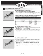
Move the motor base (
15, fig.B
) as far as possible backwards
Set the cutting depth by turning the cutting depth adjustment knob (
7, fig.B
)
Move the motor base forward and check if the pin (
A, Fig.B
) will fall in the notch
of the adjustment knob.
The following table shows the relationship of the markings on the adjustment knob
to cutting depth, the thickness of material and associated biscuit dowels.
1.
2.
3.
Marking Thickness Of Material Biscuit Size
Cutting Depth
0
8 - 12 mm
No. 0
8 mm
10
12 - 15 mm
No. 10
10 mm
20
> 15 mm
No. 20
12.3 mm
S
-
Simplex
13 mm
D
-
Duplex
14.7 mm
Max.
-
-
18 mm
ADjUSTING THE CUTTING ANGLE
The cutting angle can be set by unlocking the clamping lever (
8, fig.C
) and put
the fence stop (
4, fig. C
) in the required angle.
Should the clamping lever be in the way when working with the tool, then pull
the clamping lever out and fasten it in a different position without changing the
cutting angle.
ADjUSTING THE HEIGHT
The correct height can be set by unlocking the clamping lever (
9, fig.D
) and
turning the knob for the height adjustment (
10, fig.D
) to the desired height with
aid of the scale (
11, fig.D
).
The height must correspond to half of the material thickness of the working
piece, the groove for the biscuit dowel must always be in the middle of the
working piece.
Should the clamping lever be in the way when working with the tool, then pull
the clamping lever out and fasten it in a different position without changing the
height.


