background image

2

ENGLISH

FRANÇAIS

FRANÇAIS

ENGLISH

2

ENGLISH

FRANÇAIS

FRANÇAIS

ENGLISH

IMPORTANT SAFETY INSTRUCTIONS

13. AVOID UNINTENTIONAL STARTING.

 Be sure the switch is in the OFF 


position before plugging in.

14. ALWAYS CHECK AND MAKE SURE TO REMOVE ANY ADJUSTING KEYS 

OR WRENCHES

 before turning the tool on.  Left attached, these parts can fly 

off a rotating part and result in personal injury. 

15. DO NOT USE THE COMPRESSOR IF IT CANNOT BE SWITCHED ON OR 

OFF.

  Have it repaired before using it.

16. DISCONNNECT THE PLUG FROM POWER BEFORE MAKING ANY  

ADJUSTMENTS.

  Changing attachments or accessories can be dangerous 


if the tool could accidentally start.

17. MAINTAIN TOOLS WITH CARE.

 Keep tools clean for better and safer 


performance.  Follow instructions for lubricating and changing accessories. 

Keep dry, clean and free from oil and grease.

18. CHECK FOR DAMAGED PARTS.

 Make frequent inspections for the correct 

function of components and safety mechanism.

19. REPLACEMENT PARTS.

 When servicing, use only identical replacement parts 

and fasteners recommended by us.

20. EMPLOYERS

 must enforce compliance with the safety warnings and all other 

instructions in this manual.  Keep it available for use by everyone assigned to 

use this equipment.

COMPRESSED AIR CAUTIONS

1.  COMPRESSED AIR FROM THIS UNIT MAY CONTAIN CARBON  

MONOXIDE.

  The air produced is neither suitable for breathing nor food 

processing without filtering and testing to all applicable legal standards.

2.  AIR ONLY:

  Use this compressor for compressing air only.  Do not compress 

other gases.

3.  BREATHING PROTECTION:

  Always use a respirator when spraying paint or 

chemicals.

5.  NEVER USE THIS EQUIPMENT

 if it is leaking air; has missing or damaged 

parts, guards, or shields; or requires repair.  Make sure all screws and caps are 

securely tightened.

6.  DO NOT USE THE AIR HOSE

  to move the compressor.  Release the pressure 

in the storage tank before moving.

7.  DO NOT ATTEMPT ANY MAINTENANCE OR ADJUSTMENT

 with the com

-

pressor in operation, the power connected, or air under pressure in the system. 


1.  TANK SAFETY VALVE:

 This valve prevents damage to the air receiver if a 

malfunction in the compressor pump occurs.  It is factory pre-set at a limit 


specific to your particular model and adjustment.  Do not tamper with it. This 

will automatically void your warranty.

2.  PRESSURE SWITCH:

  The air pressure switch is factory pre-set for optimum 

performance. Do not bypass or remove this switch. Serious damage to 


equipment or personal injury could result from too high an air pressure.

3.  MOTOR AND COMPRESSOR PUMP:

  Air compressors get hot during opera

-

tion. Do not touch the motor, discharge tubing, or compressor while it is run

-

ning. 

The compressor turns itself on automatically while the power is connected.

4.  AIR TANK:

  Over-pressurizing the air receiver, piping or tank could cause 

it to explode or burst. To protect from over-pressurizing, the compressor is 

equipped with a factory preset safety valve. Do not remove, make adjustments 

to or substitutions for this valve.  Perform a test of the valve from time to time: 

pull the ring on the valve to make sure that it operates freely. If the valve does 

not operate freely, replace it before further use. Never weld to, drill into, or 

change the air receiver in any way.

5.  TAMPERING:

 If any of the components above are found to have been changed 

or tampered with, the warranty will be made void. When servicing, we recom

-

mend using only identical replacement parts and any replacement parts used 

must have the same specification as the original equipment. 

SAFETY PRECAUTIONS SPECIFIC TO COMPRESSOR

Summary of Contents for SPT280

Page 1: ...ce CONSERVEZ CE GUIDE Vous aurez besoin de ce guide pour les instructions de sécurité les procédures d utilisation et la garantie Conservez le dans un endroit sûr et sec pour référence future PROD NO 013465 MOD NO SPT280 v 081118 Air Compressor 2 in 1 Brad Nailer Stapler Kit Operator s Manual p 2 Jeu de compresseur à air et agrafeuse cloueuse 2 en 1 Manuel de l opérateur p 12 ...

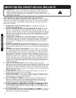
Page 2: ...vides a low resistance path to carry electricity to ground away from the operator should the tool malfunction electrically Do not remove the grounding prong from the plug or alter the plug in any way If in doubt as to whether the outlet is properly grounded accord ing to code check with a qualified electrician Extension cords must also be equipped with grounded three prong plugs 6 SAFETY GLASSES T...

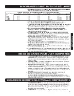
Page 3: ...or shields or requires repair Make sure all screws and caps are securely tightened 6 DO NOT USE THE AIR HOSE to move the compressor Release the pressure in the storage tank before moving 7 DO NOT ATTEMPT ANY MAINTENANCE OR ADJUSTMENT with the com pressor in operation the power connected or air under pressure in the system 1 TANK SAFETY VALVE This valve prevents damage to the air receiver if a malf...

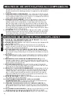
Page 4: ...rom yourself and others at all times No horseplay Respect the tool as a working implement 12 DO NOT LOAD FASTENERS with trigger or safety depressed The tool may unintentionally fire a fastener 13 DO NOT DEPRESS THE TRIGGER when not driving fasteners Never carry tool with finger on trigger mechanism tool may fire an unwanted fastener 14 DON T OVERREACH Keep proper footing and balance at all times D...

Page 5: ...Shoots all sizes of industry standard 18 gauge narrow crown staples 90 series crown up to 1 1 2 or 38 mm in length Shoots industry standard 18 gauge brad nails in the following sizes 15 mm 5 8 20 mm 3 4 25 mm 1 30 mm 1 3 16 32mm 1 1 4 40 mm 1 9 16 45 mm 1 3 4 and 50 mm 2 Padded hand grip Belt loop hook Adjustable exhaust deflector Includes S3 hex key S4 hex key Small bottle of air tool oil Tool we...

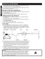
Page 6: ...regulator and an automatic oiler located as close to the tool as possible within 15 feet 5 meters is ideal Do not use bottled air or gases Please see figure below All compressed air contains moisture and other contaminants that can harm the internal components of the tool An air line filter will remove most of these and significantly prolong the life of the tool Ensure the in line oiler has suffic...

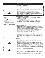
Page 7: ...the BODY 24 and press SAFETY BRACKET ASSEMBLY 29 against the work surface being sure the tool is perpendicular to the surface 4 Gently squeeze the TRIGGER 39 to drive the fastener 5 Lift the tool off the work surface 6 If a change is desired first adjust the wheel turning it to the left for greater depth and to the right for less 7 Further adjustment can be had by adjusting the compressor regulato...

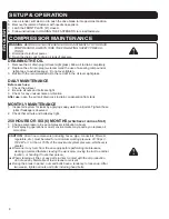
Page 8: ...ter use open the air tank drain cock to drain condensation from tank MONTHLY MAINTENANCE 1 Inspect air system for leaks by applying soapy water to all joints Tighten those joints if leakage is observed 2 Check that all nuts and bolts stay tight 250 HOURS OR SIX 6 MONTHS whichever comes first 1 Change compressor oil see compressor lubrication above 2 Paint spraying operations or dusty environments ...

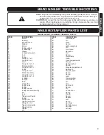
Page 9: ...Heat sink 56 Check valve 57 Drain cock 58 Flat washer 59 Cushion foot 60 Tank 61 Unloader tube nut 61a Ferrule 61b Unloader tube assembly 62 Pressure gauge 63 Pressure gauge 64 Plug COMPRESSOR PARTS LIST COMPRESSOR TROUBLESHOOTING Will not start Fuse blown or circuit breaker tripped Check for cause and replace or reset Loose electrical connections Check wiring connections Extension cord not correc...

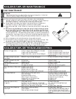
Page 10: ...her parts NAILER STAPLER TROUBLESHOOTING Air leak at trigger area O ring in trigger valve damaged or cracked Check and replace O ring Trigger valve head damaged Check and replace trigger valve head Trigger valve stem seal or O ring damaged Check and replace trigger valve stem seal or O ring Air leak between body and Piston O ring or bumper damaged Check and replace O ring or bumper front plate Air...

Page 11: ... 17 O ring 50 5 x 2 5 18 Collar 19 O ring 30 3 x 3 20 Piston assembly 21 O ring 40 2 x 2 3 22 O ring 35 6 x 1 8 23 Cylinder 24 Bumper 25 Body 26 Joint guide 27 Safety guide 28 Spring 29 Safety bracket 30 Safety bracket assembly 31 Pin 32 Seal 33 Trigger valve head 34 Spring 35 O ring 5 5 x 1 5 36 Trigger valve stem 37 O ring 15 x 1 9 38 Trigger valve guide 39 Trigger spring 40 Trigger 41 Pin ITEM ...

Page 12: ...courant mise à la terre qui convient de voltage indiqué et avec une protection par fusible Les outils mis à la terre doivent être branchés dans une prise de courant installée et mise à la terre adéquatement La mise à la terre offre un chemin de faible résistance menant l électricité à la terre loin de l opérateur si l outil avait un problème de nature électrique Ne pas enlever la broche de mise à ...

Page 13: ...e fréquentes vérifications afin de vous assurer du bon fonctionnement des com posantes et du mécanisme de sécurité 19 PIÈCES DE RECHANGE Pour le service n utilisez seulement que des pièces de rechange et de fixation identiques 20 LES EMPLOYEURS doivent faire respecter toutes les directives de sécurité et autres directives comprises dans ce manuel Gardez le manuel à la portée de tous ceux qui utili...

Page 14: ...outeille comme source d alimentation pour cet outil Cela pourrait provoquer une explosion et des blessures corpore lles graves 5 RACCORDS Branchez l outil au boyau d alimentation d air à l aide d un raccord 3 8 po NPT qui libère toute la pression de l outil lorsque le raccord est décon necté 6 DÉBRANCHEZ L OUTIL DU BOYAU D ALIMENTATION D AIR avant de procéder au démontage à l entretien à l enlèvem...

Page 15: ...OG l Poids léger 33 lb 15kg l Lubrifié à l huile pour une plus grande durabilité l Fonctionnement extrêmement silencieux l Comprend un régulateur pour la conduite d air et manomètre réglez la pres sion désirée de la conduite d air peut exiger un branchement au compresseur l Bouchon reniflard pour l huile peut exiger un branchement au compresseur l 120 volt 60 Hz 10 amp l 3400 tr min l 2 5 c f m 90...

Page 16: ... DE RALLONGE Si vous utilisez un cordon de rallonge pour faire fonctionner votre compresseur d air bien vouloir noter que l Longueur maximum ne doit pas dépasser 15m 50 pi l Grosseur maximum du fil 14 ga Si le cordon de rallonge est trop long ou le fil est trop petit le compresseur ne pourra démarrer LUBRIFICATION DU COMPRESSEUR l VÉRIFIEZ la qualité et la quantité d huile avant de faire fonctionn...

Page 17: ...era expulsée de la sortie d échappement de l outil lors du déclenchement l Raccord de conduite d air La cloueuse devrait être équipée d un raccord rapide mâle de 1 4 po NPT Pour éviter le déclenchement accidentel même si l outil est déconnecté il doit toujours être raccordé à la source d alimentation d air de façon à ce que toute la pression d air soit dégagée lorsque le raccord est déconnecté MIS...

Page 18: ...pièce de fixation 5 Soulevez l outil de la surface de travail 6 Si vous voulez modifier la profondeur d enfoncement ajustez la roue par la tourner a gauche pour augmenter la profondeur et a droit pour la diminuer 7 Plus de variation est possible par ajuster le régulateur du compresseur pour augmenter ou diminuer la pression d air Essayez d enfoncer une autre agrafe et vérifiez de nouveau la profon...

Page 19: ...ENTRETIEN MENSUEL 1 Pour vérifier s il y a des fuites au système d air appliquez de l eau savonneuse sur tous les joints S il y a une fuite serrez les joints 2 Vérifiez à ce que les écrous et les boulons sont toujours bien serrés 250 HEURES OU SIX 6 MOIS le premier qui survient 1 Changez l huile du compresseur consultez la section lubrification du com presseur ci dessus 2 Pour des opérations de va...

Page 20: ...a condition persiste remplacer la soupape Filtre à air obstrué Nettoyer ou remplacer le filtre Soupape de non retour défectueuse Remplacer la soupape de non retour Relâche de la soupape de sûreté Pressostat défectueux ou ajustement Vérifier le réglage approprié et si le problème inapproprié persiste remplacer le pressostat Fuite d huile dans l air Viscosité inappropriée de l huile Remplacer avec u...

Page 21: ...47 Ventilateur 48 Câble électrique 49 Raccord rapide d air 50 Regulateur de pression 51 Raccord 52 Pressostat 53 Soupape de sûreté 54 Poignée 55 Écrou d échappement 55a Virole 55b Ensemble de tuyau d echappement 55c Radiateur 56 Soupape de contrôle 57 Robinet de purge 58 Rondelle plate 59 Coussinet 60 Réservoir 61 Écrou pour marche à vide 61a Virole 61b Tuyau pour marche à vide 62 Manomètre 63 Man...

Page 22: ...ez et remplacez la tête de soupape du déclencheur 3 Tige de soupape joint d étanchéité ou joint torique du déclencheur endommagé 3 Vérifiez et remplacez la tige de soupape le joint d étanchéité ou le joint torique du déclencheur Fuite d air entre le corps et la plaque avant Joint torique du piston ou du butoir endommagé Vérifiez et remplacez le joint torique ou le butoir Fuite d air entre le corps...

Page 23: ...le 32 Joint 33 Tête de soupape de déclencheur 34 Ressort 35 Joint torique 5 5 x 1 5 36 Tige de soupape de déclencheur 37 Joint torique 15 x 1 9 38 Guide de soupape de déclencheur 39 Ressort de déclencheur 40 Déclencheur ARTICLE DESCRIPTION 41 Goupille 42 Rondelle de blocage 43 Goupille 44 Plaque 45 Vis 46 Ensemble de loquet 47 Goupille 48 Plaque avant 49 Barre de guidage 50 Goupille 51 Vis 52 Corp...

Page 24: ...G Repairs should be made by an authorized repair centre Opening this tool could invalidate your warranty AVERTISSEMENT Toutes les réparations doivent être exécutées par le personnel d un centre de service autorisé Si vous ouvrez cet outil vous risquez d annuler la garantie ...

Page 25: ...G Repairs should be made by an authorized repair centre Opening this tool could invalidate your warranty AVERTISSEMENT Toutes les réparations doivent être exécutées par le personnel d un centre de service autorisé Si vous ouvrez cet outil vous risquez d annuler la garantie ...

Page 26: ...e continuel Afin d obtenir une fiche des centres de service autorisé s v p consulter le catalogue ITC WARRANTY ITC branded power tools air nailers staplers and compressors are designed for use in DIY do it yourself light or intermittent duty semi professional applications They are not intended for use in professional production industrial or continual use applications ITC makes every effort to ens...

Reviews: