background image

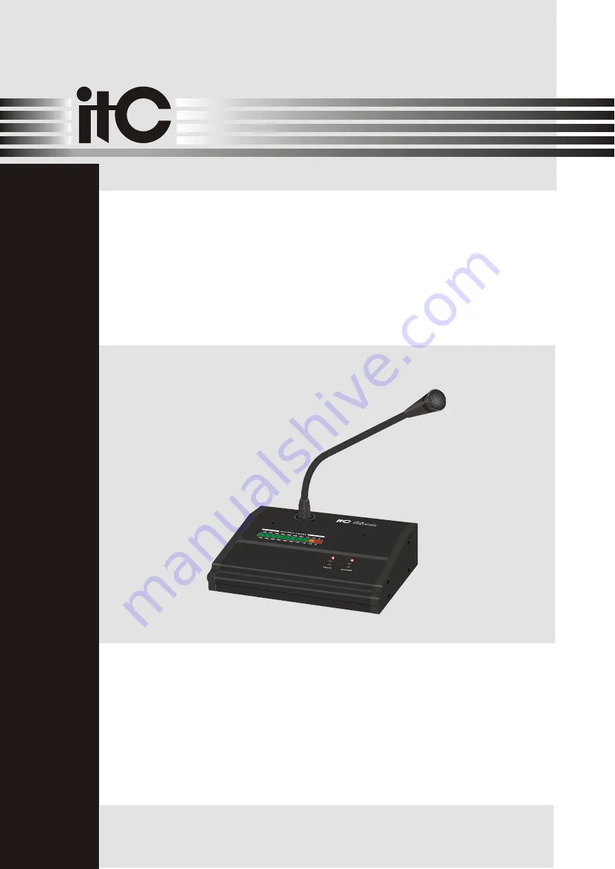
Please follow the instructions in this manual to obtain the optimum results from this unit.

We also recommend that you keep this manual handy for future reference.

MICROPHONE 

T-319

O

P

E

R

A

T

IO

N

 M

A

N

U

A

L

PUBLIC ADDRESS SYSTEM

Summary of Contents for T-319

Page 1: ...ollow the instructions in this manual to obtain the optimum resultsfrom this unit We also recommend that you keep this manual handyfor future reference MICROPHONE T 319 OPERATION MANUAL PUBLIC ADDRESS...

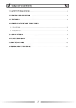
Page 2: ...TENTS 1 SAFETY PRECAUTIONS 3 2 GENERAL DESCRIPTION 5 3 FEATURES 5 4 NOMENCLATURE AND FUNCTIONS 4 1 Front Panel 6 4 2 Rear Panel 7 5 APPLICATIONS 8 6 BLOCK DIAGRAM 9 7 SPECIFICATIONS 10 8 DIMENSIONAL D...

Page 3: ...in fire or electric shock Be sure to replace the unit s terminal cover after connection completion Because high voltage is applied to the speaker terminals never touch these terminals to avoid electr...

Page 4: ...sooty smoke or steam as doing otherwise may result in fire or electric shock When the Unit is in Use Do not place heavy objects on the unit as this may cause it to fall or break which may result in p...

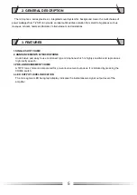
Page 5: ...ions microphone 2 GENERAL DESCRIPTION 1 3 4 SINGLE SHOT CHIME 2 ANNOUNCEMENTS BY MICROPHONE Unobtrusive and easy to use condenser type microphone which is highly sensitive and reproduces high clarity...

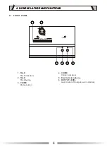
Page 6: ...me button 4 NOMENCLATURE AND FUNCTIONS 4 NOMENCLATURE AND FUNCTIONS 4 CHIME Chime indicators 5 Electret microphone 6 OUTPUT LEVEL Level meters 10 output level indicators 6 3 3 4 4 6 5 2 1 OUTPUT LEVEL...

Page 7: ...icrophone signal is for operating power of condensor microphone 10 MIC VOL MIC volume control P T T 1 7 4 52 1 3 6 4 GND PRIORITY CHIME LED PWR MIC INPUT 5 6 7 2 1 3 7 4 52 4 2 GND PRIORITY CHIME LED...

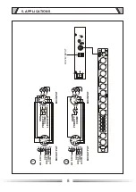
Page 8: ...5 6 7 1 3 6 CHIME REMOTE 2 OUTPUTS 1 7 4 5 2 4 2 GND PRIORITY CHIME LED PWR MIC INPUT 1 3 5 6 7 1 3 6 7 4 5 2 1 3 6 4 GND PRIORITY CHIME LED PWR MIC INPUT 5 6 7 2 1 3 4 5 2 4 2 GND PRIORITY CHIME 1 3...

Page 9: ...7 4 5 2 1 3 6 BALANCE MIC INPUT LEVEL INDICATOR AC 220V 240V 50 60Hz PT CHIME TALA CH1 CH4 BALANCE OUT DC 24V INPUT POWER ON 6 BLOCK DIAGRAM 9...

Page 10: ...PATTERN FREQUENCY RESPONSE IMPEDANCE SENSITIVITY 0DB 1V 0 1PAAT1KHZ S N RATIO GENERAL GENERAL POWER SOURCE WEIGHT DIMENSIONS 0dB unit gain 600Ohms DC 24V T 319 50dB 600Ohms 20Hz 20kHz 3dB Less than 0...

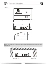
Page 11: ...LEVEL 45 45 40 40 35 35 30 30 25 25 22 22 20 20 15 15 10 10 0 0 CHIME TALK ON OFF P T T 1 0 10 MIC VOL 7 4 52 1 3 6 4 GND PRIORITY CHIME LED PWR MIC INPUT 5 6 7 2 1 3 BATT SUPPLY 24V 2A ON OFF P T T 1...

Page 12: ...PUBLIC ADDRESS SYSTEM VersionV0 1...

Reviews: