NOMENCLATURE AND FUNCTIONS
7
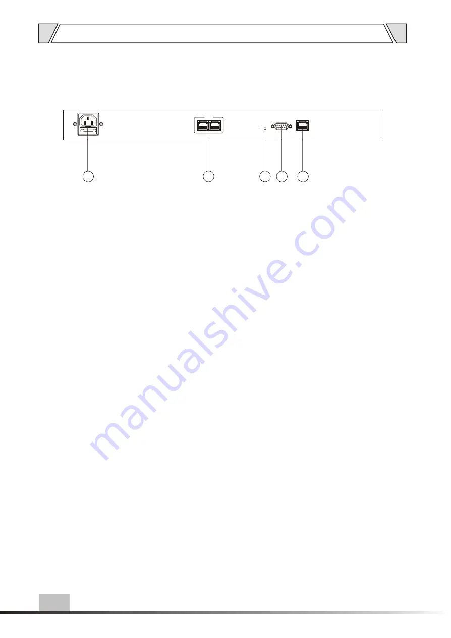
4.2 REAR PANEL
4. The network communications port (serial 2)
Intelligent interface with the fire signal connected
to the
communication network
5. The power indicator (PW)
The power is turned on, indicator light
3. ~ 220-240V 50/60Hz power in put
7. The network input (port)
With the PC host / Ethernet / switch
connected
6. The terminal configuration (serial 1)
Connected with the PC host port
5
4
6
7
3
PW
COM1
LAN
COM2


