background image

4   

www.itec-audio.com  

DIGIPOWER 2x250T

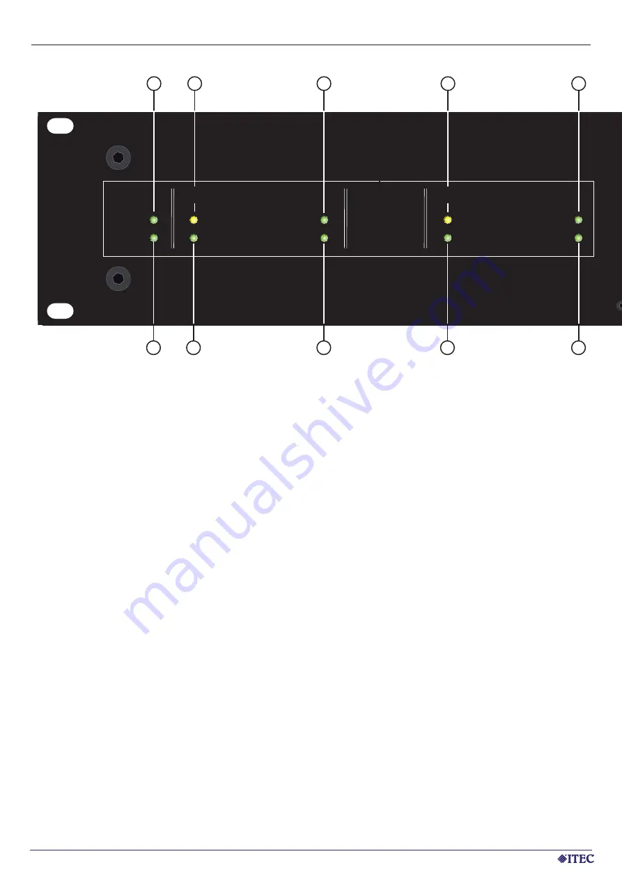
ITEC DIGIPOWER 2x250T - FRONT VIEW

Fault

Clip

Signal

Channel B

Fault

Clip

Signal

Channel A

24V DC

230V AC

Operating mode

Operating mode

10

9

8

7

6

1

2

3

4

5

1.   24V DC:    

indicates that 24V DC power is applied


2.   Channel A Fault:  

indicates a fault, e.g.: thermal overload at channel A 


During normal operation this LED fl ashes shortly after powering up until the protection mode 


is terminated and the speaker output is enabled.

3.   Channel A Clip:  

indicates an excessive input signal and the activation of the built-in limiter to prevent a clipping 

   of 

the 

signal

4.   Channel B Fault: 

as item 2, but for channel B

5.   Channel B Clip: 

as item 3, but for channel B

6.   230V AC:   

indicates that the applied voltage is 230V AC. The device is supplied by this voltage - 


the 24V DC remains unloaded.

7.   Channel A Operating Mode: 

Indicates that channel A is active. This means a signal at input A is present, 


     which is amplifi ed. If no signal is detected, the amplifi er switches to a low power  


     standby mode - the LED turns off.

8.   Channel A Signal: 

indicates that the signal is > 30dB.

9.   Channel B Operating Mode: 

as item 7, but for channel B

10. Channel B Signal: 

as item 8, but for channel B

Summary of Contents for DIGIPOWER 2x250T

Page 1: ...DIGIPOWER 2x250T POWER AMPLIFIER MANUAL VERSION 1 0 MAY 2011 Designed and Manufactured by ITEC Tontechnik und Industrieelektronik GesmbH 8200 Laßnitzthal 300 Austria Europe D DI IG GI IPOWE ER R 2x250T ...

Page 2: ... provide an effective overload protection and avoid distortion or damages of the speaker systems Short circuit and over temperature protection ensure a maxi mum operational safety Various practical details and the convenient streamlined design facilitate installation and operation Please read this instruction manual carefully and observe all instructions in particular those safeties related to ens...

Page 3: ...wire of the feeder Before connecting to the mains supply check that the data on the backside of the device match with the local network The device must necessarily be checked by trained personnel in case The power cable or plug are damaged small objects or liquids got into the device the device operates in a different way than usual the device was exposed to a severe impact or the housing has been...

Page 4: ...cessive input signal and the activation of the built in limiter to prevent a clipping of the signal 4 Channel B Fault as item 2 but for channel B 5 Channel B Clip as item 3 but for channel B 6 230V AC indicates that the applied voltage is 230V AC The device is supplied by this voltage the 24V DC remains unloaded 7 Channel A Operating Mode Indicates that channel A is active This means a signal at i...

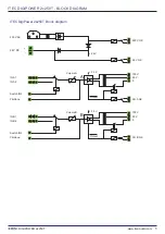
Page 5: ...R 2x250T BLOCK DIAGRAM ITEC DigiPower 2x250T Block diagram 230 V AC 24 V DC 230 V OK 24 V 24 V OK CH A OK 100 V 50 V 0 IN A1 IN A2 Switch IN2 Pilottone Protect 24 V Volume A A CH B OK 100 V 50 V 0 IN B1 IN B2 Switch IN2 Pilottone Protect 24 V Volume B B ...

Page 6: ...t the 24V DC input is kept at a minimum level 40mA for measurements 13 CH A Volume Volume control for channel A adjustable with a little screwdriver 14 A IN1 Balanced signal input for channel A 15 A IN2 Second symmetrical signal input for channel A If the corresponding terminal is Switch IN2 to set to GND this signal is alternatively used instead of A IN1 16 SWITCH IN2 Used for switching from A IN...

Page 7: ... A I A I 2 GND GND GND A IN2 A I A IN2 N2 A IN1 A I A IN1 N1 GND GND GND A IN1 A I A IN1 N1 PILOT TONE PILO PILOT T T TONE ONE SWITCH I 2 n SWITCH SWITCH I 2 I 2 n B I 2 n B B I 2 I 2 n n GND GND GND B IN2 B IN B IN2 2 B IN1 B IN1 B IN1 GND GND GND B IN1 B IN1 B IN1 CH B CH CH B CH A CH CH A 24V OK 24V OK 24V OK CH A OK CH CH A O A OK CH B OK CH B OK CH B OK 230V OK 230V OK 230V OK Made Germany in...

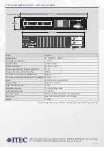
Page 8: ...TIONS ARE ONLY ALLOWED AS SHOWN RISK OF ELECTRIC SHOCK DO NOT OPEN BEFORE DISCONNECT MAINS PLUG TYPE 2x250T Output Power 2 x 250 W or 1 x 500 W Total Harmonic Distortion 0 2 Input sensitivity 1V 10 kOhm Output transformer 2 x 50 V 100 V Power consumption in standby mode 230V 10 W Power consumption at full load 230V 630 W DC current consumption in standby mode 400 mA DC current consumption during 2...

Reviews: