background image

ITEC SPIDERMIKE 2


 www.itec-audio.com     

9

SPIDERMIKE 2

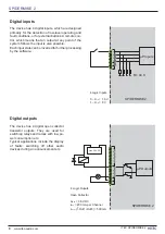
External control inputs

At the external control inputs a voltage of 0 – 10 
V is measured. These values can be used as 
a local gain control for the audio inputs of the 
according device or as a control variable for the 
output volume of any device in the network.

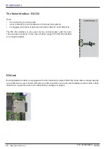
Ethernet interfaces


SPIDERMIKE 

2

Network

B

A

Redundant Network

Ethernet Unit

The network connection is carried out via socket A by default. 
If a link to second redundant network is planned, socket B is used.
The LEDs on the RJ45 connector show the operating status of the network connection:

Green LED on: Connected
Green LED 

fl

 ashing: Connected and network activity

Yellow LED on: valid connection (100Mbps full duplex)


A/D-

Converter

R

i

= 44 K

 10 K

6 External Controls

SPIDERMIKE 2

Summary of Contents for ITECNET SPIDERMIKE 2

Page 1: ...SPIDERMIKE 2 MANUAL VERSION 1 0 MAY 2011 2 S S S SP P P P PI ID DERMIKE 2 Designed and Manufactured by ITEC Tontechnik und Industrieelektronik GesmbH 8200 La nitzthal 300 Austria Europe...

Page 2: ...its function as a base station a large number of monitoring and control functions The integrated SD card reader player allows the storage and playback of alarm texts announcements jing les or even who...

Page 3: ...timber furniture is not allowed When connecting to other devices e g sound sources computers the exact pin configuration and the spe cifications of inputs and outputs need to be observed Only a connec...

Page 4: ...twork ITECNET ITECNET is a decentralized Ethernet based audio network for the simultaneous transmission of up to 64 audio channels with the highest audio quality At the same time a huge number of syst...

Page 5: ...ersion DSP version of the software OnTime Total running time of the device SpiderMike 2 the station of ITECNET system is unique in terms of flexibility and features Due to its modular expandability th...

Page 6: ...Ethernet 4 Logic Inputs 4 Logic Outputs 6 External Controls 0 dB 30 dB VCA 20 dBs 12 V IN 1 P P 1 2 3 OUT 1 Ethernet Unit Feed CH 1 256 Get CH 1 256 A D Converter Input Matrix OUTPUT UNIT 1 MIX Volume...

Page 7: ...d Phantom power is switchable per channel 12V Connection is made to the included power adapter or an existing 24 V DC emergency power supply The ground connection of the device audio ground and ground...

Page 8: ...for further processing by the software SPIDERMIKE 2 Digital inputs Digital outputs The device has 4 digital open collector transistor outputs They are used for switching relays and lamps with low po...

Page 9: ...ice in the network Ethernet interfaces SPIDERMIKE 2 Network B A Redundant Network Ethernet Unit The network connection is carried out via socket A by default If a link to second redundant network is p...

Page 10: ...32 interface is also used for the communication with the inter com expansion modules In this case a further usage of the RS 232 interface is no longer possible RX SPIDERMIKE 2 SD Card Each SpiderMike...

Page 11: ...ough expansion modules each with 24 keys In total up to four expansion modules each with 24 keys can be combined to the 19 key base station resulting in a maximum number of 115 keys The station Spider...

Page 12: ...der Compressor limiter Filter quality selectable from 0 1 to 70 SERIAL INTERFACES RS 232 9600 19200 57600 115 200 baud DIGITAL INPUTS 4 schmitt trigger inputs on plug in terminal strip INPUT VOLTAGE L...

Reviews: