POWERMIX 6/3 DIGITAL
www.itec-audio.com
POWERMIX 3/6 DIGITAL
7
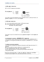
4. XLR-output connectors
OUT2 - OUT3: balanced Line-outputs.
Pin assignment:
1……. ground
2.…....
3........ signal –
If you need to connect the balanced out to an unbalanced input (e.g. phone jack input), use
ground
and
. Pin 3, don’t connect
Signal-
5. XLR-input connectors
IN1 - IN2: balanced Microphone inputs, 12V Phantom power
IN3 - IN5: balanced inputs, optional Line/Mic.,
switchable 12V phantom power
Pin assignment:
1……. ground
2.…....
3........ signal –
If you need to connect an unbalanced input, use
ground
and
. Connect
signal-
with
ground
!
6. Loudspeaker connector „SPEAKER OUT 2“ (optional)
This connector could be used if the optional component „ITEC POWER BOOST 2“
is installed. Pin assignment and features are equal to „SPEAKER OUT 1“ (see item
no. 3).
7. Antenna connector (optional)
This connector is available if the optional component „radio frequency receiver” is
installed!
BNC-jack to directly connect an antenna or a coaxial aerial line.
For each installed receiver there are 2 jacks installed.
Use the supplied antennas or order special ground-plane antennas with
corresponding cables.
Hint: If you use devices with a “
i
“-label, the “LINE-IN”, “LINE-OUT” and RS232
connectors are arranged on the rear panel (described in section 2).
Fig. 3 output connector
Fig. 4 input connector
Summary of Contents for POWERMIX 6/3 DIGITAL
Page 1: ......


