background image

9  /  13 

4. Usage

Now that you have connected your console and servers to your KVM Switch, it is ready for use. 

You can control the KVM switch by two methods:   

1.

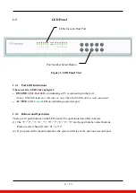
Using push buttons located on the LED panel of the KVM Switch

2.

Using hot-key commands through the console keyboard

It takes few seconds for the video signal to refresh after switching servers. Re-synchronization of 

the mouse and keyboard signals also occurs. This is normal operation and ensures that proper 

synchronization is established between the console and the connected servers.


4.1


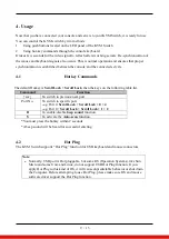
Hotkey Commands 

The default Hotkey is 

Scroll Lock + Scroll Lock

, then the keys on the following table list. 

Command


Function


↑ or ↓


To switch to previous/next port 

Port No. 

To switch to specific port 
-e.g. Port 4: 

Scroll Lock + Scroll Lock + 0 + 4 

-e.g. Port 12: 

Scroll Lock + Scroll Lock + 1 + 2 

B


To enable/disable 

beep sound 

function. 

S


To activate the 

Auto-scan 

function. 

*You must press the hotkey within 2 seconds

*A beep sound will be heard for successful entering

4.2


Hot Plug 

The KVM Switch supports “Hot Plug” function for USB keyboard and mouse connectors. 

Note

Normally, USB port is Hot pluggable, but some OS (Operation Systems), like Sun
Micro and some Unix and Linux, do not support USB Hot Plug function. If you
apply Hot Plug to this kind of OS, it will cause unpredictable behavior or shut down
the Computer. Before attempting to use Hot Plug, please make sure OS and mouse
software driver support the Hot Plug function.

Summary of Contents for AMil-1900-D12e-AC

Page 1: ...RU 19 LCD Console Drawer with Integrated DVI D KVM Switch 12 Port Military Grade User Manual MODEL AMil 1900 D12e AC i Tech Company LLC EMAIL info itechlcd com WEB www iTechLCD com Modified 04 05 2022...

Page 2: ...1 4 Back Panels 5 1 5 Front USB for External Keyboard Mouse 5 2 Hardware Installation 6 2 1 Computer Server Installation 6 2 1 1 Connecting KVM switch to the host system 6 2 2 Power Up Sequence 7 3 Ra...

Page 3: ...ters Additional one USB console port to add local KB Mouse front Supported video resolution up to 1280 x 1024 Support Microsoft Windows Unix and Linux Mac OS Support hardware HP IBM Dell PC Server and...

Page 4: ...B cable is well connected ACTIVE LED Green LED on indicating a selected port 1 3 2 Buttons and Operations There are 10 push buttons on the LED panel The operations described in below 1 The 1 2 3 4 5 6...

Page 5: ...s Figure 2 Back Panel View 1 5 Front USB for External Keyboard Mouse It provides one front port USB for external keyboard or mouse AC Power lock connector Connector for each Host Port USB Keyboard or...

Page 6: ...nect the KVM switch of the host system performs the following steps Step 1 Power up you KVM Switch by connecting the power cord to it Step 2 Connect the shared USB keyboard mouse to the KVM switch Ste...

Page 7: ...orrectly The recommended Power Up sequence is as follows Monitor KVM Switch finally the computers Verify that all servers connected to the KVM Switch are powered on If any connected servers have not b...

Page 8: ...the LCD console drawer so the two rear slide rails will slide into the main body of the LCD console drawer Attach the mounting ears of the LCD console drawer to the front vertical mounting rails of th...

Page 9: ...on the following table list Command Function or To switch to previous next port Port No To switch to specific port e g Port 4 Scroll Lock Scroll Lock 0 4 e g Port 12 Scroll Lock Scroll Lock 1 2 B To e...

Page 10: ...280 x 1024 Computers Selection 1 Hotkey 2 Push button Hotkey Scroll lock Computer Port LED s 2 x LED s per Host port ON LINE Red ACTIVE Green Auto Scan Intervals Fixed time Local console Front 1 x USB...

Page 11: ...tor Connect another monitor directly to the server to verify that your monitor is functioning properly Please check if all connectors are connected properly The power adapter is not connected to the K...

Page 12: ...on between a monitor and a video adapter Using DDC a monitor can inform a computer s video card about its properties such as maximum resolution and color depth to ensure that the user is presented wit...

Page 13: ...his device may not cause harmful interference 2 This device must accept any interference received Include interference that may cause undesired operation CE This equipment is in compliance with the re...

Reviews: