6
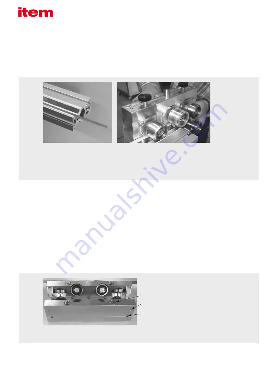
Use the roller assembly tool to bead the aluminium ribs and fix
the steel strips in place. Start at the top of the profile then turn
the profile and repeat at the bottom.
Insert the steel strips into their intended
positions.
Fastening screws
Maintenance openings
Adjusting screws
1. Preparation – Profile 8 80x40 KRF and steel strip:
Cut four M8x20 threads into the core bores at both ends of the Profile 8
80x40 KRF.
Next, insert the steel strips between the mounting ribs provided.
The steel strips should be approximately 5 mm shorter than the support
profile.
A roller assembly tool is used to secure the steel strips in place.
Steel strip, hardened, in a 50 m roll: L
steel strip
= L
profile
- 5mm
2. The carriage:
Solid, rigid sliding carriage made from high-quality aluminium alloy with rollers
arranged in a criss-cross pattern to absorb loads in the form of radial forces.
The carriage is supplied as a preassembled construction kit with one side
that is screwed firmly in place while the opposite side is a floating bearing
end.
The floating bearing end incorporates two adjusting screws with anti-clock-
wise fine threads for moving and adjusting the floating bearing end.
Consequently, the floating bearing is secured by turning clockwise, as usual
(turn towards the track on the profile). Turn anti-clockwise to loosen.
Slot the carriage onto the ready-prepared profile, pushing in the spring-
mounted felt pieces a little to stop them getting damaged.
Tighten the adjustable side (floating bearing end) of the carriage alternately
until the carriage is play free.
Careful adjustment is required to eliminate play when assembling the bearing.
Next, move the carriage along the entire length of the axis and check that it
is free from play.
Once the carriage is free from play, use the fastening screws to tighten the
adjustable carriage side (tightening torque, M8: 25 Nm).
Retrospective adjustments can be made at any time, as long as the screws
are accessible.


