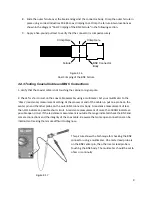
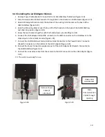
background image

5.2 Field Of View 

A


proper


"Field


Of


View"


(FOV)


is


crucial


for


optimal


Vantage


system


operation.


The


following


basic


FOV


guidelines


will


help


the


user


to


obtain


optimal


Vantage


system


performance.


There


are


two


parts


to


obtaining


an


appropriate


FOV:


Physical


camera


mounting


adjustment


Electronic


camera


lens


adjustment


5.2.1 Physical Camera Adjustment 

The


camera


should


be


mounted


so


that


it


is


centered,


as


much


as


possible,


in


relation


to


the


field


of


view


(vehicle


approach).


Extreme


side


shooting


can


result


in


reduced


performance


and


vehicle


occlusion.


See


the


section


in


this


manual


on


"Occlusion"


for


more


information.


Figure


5.8


Very


Poor


Mounting

 ‐ 

Side


Shoot,


Camera


Not


Centered


Proper Mounting Height 

The


camera


should


be


mounted


at


approximately


30


feet


for


optimal


system


performance.


For


lower


mountings,


like


a


mast


arm


mount,


a


suitable


camera


extension


bracket


should


be


used


to


increase


the


camera


mounting


height


to


a


more


workable


elevation.


A


camera


mounting


height


of


25


feet


or


more


can


usually


be


obtained


by


using


an


extension


bracket.


Low


mounting


heights


can


result


in


reduced


system


performance


and


vehicle


occlusion.


See


the


section


in


this


manual


on


"Occlusion"


for


more


information.


How


far


can


the


camera


typically


see


out


at


a


mounting


height


of


30


feet?


The


basic


formula


for


LEVEL


ground


is:


For


every


one


foot


of


height


you


can


see


out


10


feet.


So,


on


level


ground,


at


a


30


foot


mounting


height,


you


should


be


able


to


get


accurate


detection


as


far


as


three


hundred


feet.


This


measurement


is


from


the


camera


mounting


location,


not


from


the


intersection


stop


bar


area.


14


Summary of Contents for RZ4 Advanced

Page 1: ...RZ4 Advanced Installation Guide 493470301 Rev B March 2009 ...

Page 2: ...ocessor 7 4 4 3 Testing Coaxial Cable and BNC Connections 9 5 Camera Installation 10 5 1 Camera Mounting 10 5 1 1 Occlusion 13 5 2 Field Of View 14 5 2 1 Physical Camera Adjustment 14 5 2 2 Electronic Camera Adjustment 17 5 2 3 LAM Adapter Kit Components 18 5 2 4 LAM Harness Adapter Cables 18 5 2 5 Installing the LAM Adapter Module 19 5 2 6 Installing the LAM Harness Adapter 21 5 3 Electronic Came...

Page 3: ... to your existing LAM set up and configure the camera FOV on the ground 2 Features and Benefits Specifically designed for vehicle detection applications Optimized to work with Iteris advanced detection algorithms Quick click connectors and adjustable camera mount streamline installation and minimize setup time no crimping tools required Set up and configure at the camera or from the ground Cable t...

Page 4: ...ng the Vantage video detection system 1 Correct Coax and Power Cable a Video coaxial cable Belden 8281 b Power cable 3 conductor 16 gauge stranded wire 2 Surge Protection Installed properly grounded 3 Camera Installation a Use 3 stainless steel bands to mount the pedestal bracket on the luminaire arm b Power connection on camera backplate Correct pin assignment c Video connection on camera backpla...

Page 5: ...nd Power Cable Installation This procedure describes how to install the coaxial and power cables between the camera mounting location and the traffic control cabinet If you are installing multiple cameras perform the procedure for each camera The procedure is divided into the following parts 1 Running the cables 2 Preparing the coaxial cable connectors 3 Preparing the power cable connectors 4 Prep...

Page 6: ...ra 3 3 8 4 Camera 4 4 7 Cable and Camera Numbering 4 3 Camera Connections Remove the cap from the back of the camera by loosening the three screws The system is provided with a simple Quick Click connection for the power and a terminal block for the video output Loosen screws to remove backplate Bucket Truck LAM Video Connection Video Out Connection Power Input Connection Bucket Truck LAM Control ...

Page 7: ...igure 4 5 5 Remove power connector from ship kit 6 Install the conductors in the connector as per drawing figure 4 6 Ensure polarity of conductors is correct NOTE Failure to install the conductors correctly could result in camera damage and create an electrical shock hazard 7 Insert the plug into the connector on the back of the camera figure 4 7 8 Tighten the large cord grip Large Cord Grip Figur...

Page 8: ...ord grip 5 Feed cable into video connector figure 4 10 6 Tighten video connector right side of terminal block figure 4 10 NOTE The open connector space to the left of the video connection is not used and is only to provide mechanical rigidity to the terminal block 7 Replace coax cable clamp and tighten screws figure 4 11 8 Tighten small cord grip 9 Replace the cap on the back of the camera and tig...

Page 9: ... should be sized appropriately for the load current Figure 4 12 Figure 4 13 Camera Power Connections Using AC Power Plug On the End a Surge Protected Power Strip of the Camera Power Cable NOTE When calculating camera current requirements remember that the Vantage standard RZ 4 Advanced camera is rated at 25 watts max 4 4 2 Video BNC Connector for connection to Edge Processor Figure 4 14 Piece Amph...

Page 10: ...rom the coaxial shielding and flare the shielding slightly 5 Strip 125 from the coaxial dielectric 6 Insert the male contact pin so that it butts up against the dielectric crimp it in place using an Ideal Industries 30 483 coax crimping tool 7 Insert the connector body assembly over the dielectric and shielding and snap it into place Make sure the center pin is completely seated in the connector b...

Page 11: ...ing a multimeter Set your multimeter to the ohms resistance measurement setting At the processor end of the cable run put one probe on the center pin and the other probe on the outer BNC connector body A resistance measurement of less than 15Ω indicates a possible short circuit A resistance measurement of more than 500kΩ indicates a possible open circuit If the resistance measurement is outside th...

Page 12: ...that is banded to the luminaire arm or can be mounted on the mast arm using a suitable extension bracket Figure 5 1 One possible camera mounting location is up on the luminaire arm centered over the field of view however it is not always possible to use this mounting Camera mounting is critical to providing the proper field of view something that will be discussed in detail in the next section 10 ...

Page 13: ...rt to center the camera over the field of view especially on wide roadways then an extension bracket on the mast arm may be the better choice Centering the camera is just as important as gaining camera height The mast arm mounting would end up with a camera height of about 25 feet when using a 6 foot extension bracket Luminaire Arm Mounting with Pelco Bracket Figure 5 3 11 ...

Page 14: ...echnical Information section for more information PELCO Astro Brac 74 inch Camera Extension Bracket Mast Arm Mounting AB 0175 5 96 ALO Figure 5 5 PELCO has several models depending on band or cable mounting and with or without service outlet Contact your local PELCO dealer for more information on these brackets ...

Page 15: ...5 1 1 Occlusion Consequences of Low Camera Mounting Height Occlusion caused by low camera mounting height Figure 5 6 Figure 5 7 13 ...

Page 16: ...ing Height The camera should be mounted at approximately 30 feet for optimal system performance For lower mountings like a mast arm mount a suitable camera extension bracket should be used to increase the camera mounting height to a more workable elevation A camera mounting height of 25 feet or more can usually be obtained by using an extension bracket Low mounting heights can result in reduced sy...

Page 17: ...oper Camera Angle The physical camera adjustments are done by adjusting the camera bracket mounting bolts to set the mechanical camera pan and tilt after the camera bracket has been mounted to the arm or pole The camera should always be tilted slightly downward and should never be flat or beyond horizontal When could a camera be in danger of being beyond horizontal When the camera is aiming uphill...

Page 18: ...m the top of the screen to the bottom of the screen By loosening the two hose clamp set screws the camera body can rotate to better square up the FOV image The car bumpers should also end up being parallel with the bottom of the screen Figure 5 12 Figure 5 13 The Camera Body Could Be Rotated The above picture shows an acceptable To Help Square Up The Stop Bar Area FOV and stop bar area alignment ...

Page 19: ...ound through the video coax cable To enable current LAM LAMView modules to take advantage of this feature a LAM Adapter module has been developed The following diagram shows how the LAM Adapter is used in the case where the lens control is conducted from the controller cabinet ground level Power Video Comm Video Lens Control GroundLevel Camera LAMView Figure 5 14 If however the RZ4 Advanced camera...

Page 20: ...5 2 3 LAM Adapter Kit Components Figure 5 16 5 2 4 LAM Harness Adapter Cables Figure 5 17 18 ...

Page 21: ...the thumbscrews provided figure 5 21 6 Connect the LAM Adapter Video BNC connector to the BNC connector on the LAMView or to the Video input on the cabinet monitor figure 5 22 7 Connect the LAM LAMView Communication Cable Connector to the Power Comm Connector Deutsch Connector on the bottom of the LAM Adapter figure 5 22 8 Connect the Power Connector supplied as part of the LAM Adapter kit Deutsch...

Page 22: ...lide into position Tighten Thumbscrews Figure 5 21 Connect LAM Comm Cable to LAM Adapter Connect LAM Adapter Video to LAM Connect Video from Camera to BNC Connector Figure 5 20 Figure 5 22 Power Connector to LAM Connect ...

Page 23: ... back of the camera remove through cord grip figure 5 26 NOTE If the power to the camera has not been turned off this connector will be energized Please handle with extreme caution Electrical shock hazard exists 5 Attach Power Comm Video Adapter Cable to the back of the camera figure 5 26 6 Connect the Comm Deutsch Connector Video and Power from the Camera to the LAM LAMVIEW figure 5 27 7 Restore ...

Page 24: ...tach Power Adapter Cable Attach Video Cable Figure 5 26 LAM Video Connection LAM Power Connection LAM Comm Connection Remove Camera Power Connection Connect Video using BNC Barrel Connect Power Connect Comm Figure 5 27 ...

Page 25: ...LAM Harness Block Diagram Remove cable if attached Figure 5 28 23 ...

Page 26: ...It is best to wait till traffic is stopped before attempting to Auto Focus A pink rectangular shape will appear in the lower right corner of the monitor image indicating that the camera is trying to focus Never press any other buttons while the rectangular focus indicator is still visible 4 When proper focus has been obtained you must save the camera settings To do this press the LAM Set Button Th...

Page 27: ...c Considerations Regarding Proper Field of View FOV The Stop Bar Four Lane Minimum Rule This rule states that if the region of interest is less than four lanes for instance a two lane side street the FOV should still remain approximately four lanes wide Why It has to do with vehicle size if you zoom in the FOV to less than a four lane width the vehicles become too large If the vehicles are too lar...

Page 28: ...ise or sunset the sun can completely blind the camera Proper FOV visor adjustment and camera tilt can prevent this potential problem Poor Setup Horizon Is Included As Part of The Field of View FOV Figure 5 30 2 Make sure the stop bar area is located toward the bottom of the FOV This will also leave room for advance zone detection The following example photo shows the stop bar area located in the m...

Page 29: ...onitor Vertical Hold Adjustment Some monitors do not show the user the true field of view therefore it is actually possible to have horizon in the FOV and not realize it If the monitor has a vertical hold adjustment control roll the picture up and down to see everything that is actually contained in the frame When purchasing a monitor for use with the Vantage systems it is recommended that you buy...

Page 30: ... the surge protection device is available in the Technical Information section of this manual All surge protection must be approved by Iteris for use with the Vantage video detection systems Failure to install surge protection or using non approved surge protection devices will void the Vantage equipment warranties REMEMBER The surge protection device must be grounded to operate correctly Failure ...

Page 31: ...on The following section contains detailed technical information on the Vantage Edge2 Processor and its associated components Belden Coaxial Cable Power Cable Camera Bracket EDCO Surge Protection 6 1 Belden Coaxial Cable 29 ...

Page 32: ...6 2 Sample Power Cable 30 ...

Page 33: ...31 ...

Page 34: ...using high strength 6061 aluminum For added protection the assembly is gray powder coated FEATURES BENEFITS Universal Camera Mounting Horizontal for luminaire arm mounting Vertical for standard pole mounting High strength light weight aluminum construction Easy pan tilt angle adjustment Three banding slots for stainless steel banding of up to inch Vertical Mount Horizontal Mount Iteris Universal C...

Page 35: ...6 4 EDCO Surge Protection 33 ...

Page 36: ...s Cleaning the glass ensures optimal performance The use of a soft cotton cloth non abrasive and water is the recommended method for camera glass cleaning Avoid leaving streaks on the glass Avoid anything that might scratch the glass cloud the glass or leave an undesirable residue Connector and Cable Inspection Periodically it is wise to check camera power and video connections Look for connector ...

Reviews: