background image


Camera User Guide


12


2.5


Cabinet Connections 

Power Connection (Power Surge Panel) 

In the controller cabinet, AC power will need to be provided to each of the Vantage cameras. It is best to 

power the cameras from auxiliary breakers, to make sure that any damage to the camera power cables does 

not affect intersection cabinet power or controller operation.  
The power panel should also include a surge protection device to minimize possible damage to the camera 

from various power surges and transients. 


Important:


A/C Power must be fused or connected to circuit breaker.


a.


Mount the Power Panel Assembly on the inside of the cabinet in close proximity to the camera 

power cables and the AC power source. Make sure all the circuit breakers are in the “Off” position. 

b.


If you are using stranded wire, you should tin the wire ends with solder before clamping them down 

in the terminal block. Connect the individual camera power cable wires to the appropriate terminal 

block on the Power Panel Assembly. There are three wires in each camera power cable: (AC+) Hot, 

(AC-) Neutral, and Chassis Ground. The camera power cable chassis ground wire goes to the camera 

chassis ground block on the Power Panel Assembly, the camera power hot wire (AC+) goes to one of 

the circuit breakers on the Power Panel Assembly, and the camera power neutral wire should be 

terminated to the camera power neutral (AC-) terminal block on the Power Panel Assembly. 


Note:  


All circuit breakers and or fuses should be sized appropriately for the load current.


Note:  


When calculating camera current requirements remember that the Vantage standard RZ-4 

cameras are rated at 25 watts max.


Summary of Contents for Vantage RZ4 Series

Page 1: ...Part Number 493470301 Rev E ...

Page 2: ... and the author make no claim to these trademarks While every precaution has been taken in the preparation of this document the publisher and the author assume no responsibility for errors or omissions or for damages resulting from the use of information contained in this document or from the use of programs and source code that may accompany it In no event shall the publisher and the author be li...

Page 3: ... been optimized for use in outdoor conditions specifically for the viewing of traffic flows at the intersection on the highway on bridges or in tunnels The camera s image is normally adjusted to view up to 4 or 5 lanes of traffic The RZ4 AdvancedTM our new premium camera offering that provides for streamlined installation by eliminating the Amphenol and BNC connectors only wire stripping tools and...

Page 4: ...etection zone you designate the four corners of a zone on the video picture and then setup the various zone properties You can define up to 24 detection zones per camera view The processor module analyzes the camera image to determine when a vehicle is present in a zone Vehicle detection information is passed to the traffic control equipment for real time adaptive control Video can also be sent vi...

Page 5: ... 16 AWG power cable Cord grip or other watertight fitting Important Please refer to Section 6 TECHNICAL INFORMATION for information on the correct type of power and coax cable to use Failure to use the correct cable may result in poor performance or a non working system Tools Required for Installation The following tools are required for installation of the Edge2 processor Coax Crimping Tool o Ide...

Page 6: ...Camera User Guide 6 Bucket truck Video monitor patch cable Vantage Lens Adjustment Module Volt Ohmmeter ...

Page 7: ...unted on the mast arm using a suitable extension bracket One possible camera mounting location is up on the luminaire arm centered over the field of view however it is not always possible to use this mounting Camera mounting is critical to providing the proper field of view something that will be discussed in detail in the next section Possible Camera Mounting Location ...

Page 8: ...e mast arm may be the better choice Centering the camera is just as important as gaining camera height The mast arm mounting would end up with a camera height of about 25 feet when using a 6 foot extension bracket Note See the Section 6 Technical Information for more information on camera brackets Camera height should be at least 25 8m above the roadway Approximately 12 30cm from the luminaire hea...

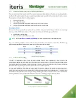
Page 9: ... the location label the camera locations and cables The following table shows a suggested numbering scheme for a location with four cameras Cable Camera Phases 1 Camera 1 2 5 2 Camera 2 4 7 3 Camera 3 6 1 4 Camera 4 8 3 Cable and Camera Numbering 2 3 Camera Grounding In order to successfully deter these transient voltage threats your equipment s input circuitry has incorporated devices that will d...

Page 10: ...he insulation from the three conductors back 6mm b Loosen the large cord grip and thread power cable through c Remove power connector from ship kit and install the conductors in the connector as per drawing Ensure polarity of conductors is correct Important A C Power must be fused or connected to circuit breaker CAUTION Failure to install the conductors correctly could result in camera damage and ...

Page 11: ...er conductor for insertion into the video connector c Feed cable through small cord grip and into video connector and tighten connector Note The open connector space to the left of the video connection is not used and is only to provide mechanical rigidity to the terminal block d Replace coax cable clamp and tighten screws Tighten small cord grip e Replace the cap on the back of the camera and tig...

Page 12: ...the circuit breakers are in the Off position b If you are using stranded wire you should tin the wire ends with solder before clamping them down in the terminal block Connect the individual camera power cable wires to the appropriate terminal block on the Power Panel Assembly There are three wires in each camera power cable AC Hot AC Neutral and Chassis Ground The camera power cable chassis ground...

Page 13: ...ng the presence of AC power e Carefully turn On each one of the four camera power breakers The breakers should not trip and each of the cameras should now have AC power Video Connector BNC connection to Edge Processor Piece Amphenol BNC Connector a Slide the outer ferrule of the Amphenol BNC connector over the coax cable b When you cut the coaxial cable it is best to use cable cutters to obtain a ...

Page 14: ...ody Crimp the outer ferrule in place using an Ideal Industries 30 483 coax crimping tool Crimp the ferrule in two locations as shown in the diagram Final Crimping of the BNC Ferrule in the following section i Apply a five pound pull test to verify that the connector is crimped securely j Connect the BNC to the back of the camera Belden Coaxial Cable with Amphenol BNC Connector Final Crimping of th...

Page 15: ...the surge protection device is available in the Technical Information section of this manual All surge protection must be approved by Iteris for use with the Vantage video detection systems Failure to install surge protection or using non approved surge protection devices will void the Vantage equipment warranties Important The surge protection device must be grounded to operate correctly Failure ...

Page 16: ...creen Car bumpers parallel to bottom of screen Adequate area left for advanced detection Occlusion A major issue with camera FOV is occlusion If large vehicles block lanes or smaller vehicles then detection will not be possible Horizon You never want the horizon to be included as part of your camera field of view If the horizon is visible as part of your field of view on East and West approaches t...

Page 17: ...nes should be drawn within the lane lines and should be the size of a medium vehicle Examples of Good FOVs Physical Camera Adjustment Centering the Camera The camera should be mounted so that it is centered as much as possible in relation to the field of view vehicle approach Extreme side shooting can result in reduced performance and vehicle occlusion See the section in this manual on Occlusion f...

Page 18: ... Note The importance of camera centering versus camera height deserves some further discussion It must be recognized how important centering the camera is to optimal system performance In many cases centering the camera is more important than getting an additional five feet of height For instance when dealing with a short luminaire arm on a very wide roadway it might be a better choice to mount th...

Page 19: ...ield visor far enough forward to give the camera maximum protection from the sun By loosening the two hose clamp set screws the camera body can be moved backward in the clamps effectively lengthening the sun shield visor Move the camera body back all the way or until the edges of the sun shield visor are just barely visible in the top left and right corners of the field of view See the following e...

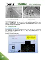
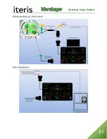
Page 20: ...ce A camera that is out of focus can significantly reduce the Vantage systems ability to perform so it is important to take the time to adjust the focus properly 3 2 Camera Adjustment Lens Adjustment Module LAM Hook Up Camera adjustment is achieved using the Lens Adjustment Module LAM There are various versions of this device the latest being the ADVANCED LAM Please refer to the user manual provid...

Page 21: ...Camera User Guide 21 RZ4 Advanced Hook Up Direct Connect RZ4 C and M Hook Up ...

Page 22: ...ned you must save the camera settings To do this press the LAM Set Button The Save Light on the LAM module should illuminate indicating the settings are being saved Do not press any buttons while the Save Light is still on If the camera settings are not properly saved the camera will return to its factory default settings whenever camera power is cycled e This completes the camera setup process Di...

Page 23: ...o ohms or continuity Symptom B I cannot zoom and focus my camera with the LAM i Are the camera power cables and video cables connected correctly Recheck the cable connections by referring to the previous diagrams and table found in this section ii Is the cabinet monitor connected adjusted correctly and plugged in to a valid working power source iii Is power correctly connected to the camera See th...

Page 24: ...he pins should be installed to create a water tight connector Symptom D Noise on the monitor i Most common cause is a faulty BNC connector at the camera ii A loose common or faulty ground in the traffic signal system can induce AC voltage onto the coax cable iii A splice in the coax cable located in a pole If not properly insulated it can pick up stray voltage or possible create a difference in gr...

Page 25: ...or video inputs are set to HiZ then video may bleed over to adjacent channels 5 MAINTENANCE The Vantage Video Detection System once correctly installed requires a minimal amount of maintenance Camera Cleaning Because Vantage video detection is a machine vision based system one of the big operational concerns is keeping the front camera glass reasonably clean A regular maintenance program should be...

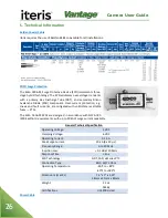
Page 26: ...e mitigated with solid state resettable fuses PTCs The Edco CX06 M SPDs are designed in accordance with NFPA 780 2004 edition requirements with up to 20 kA of surge current capability General Technical Specification Operating Voltage 5 VDC Clamping Voltage 6 VDC Operating Current 0 15 A Peak Surge Current 20 kA 8 x 20 μs Frequency Range 0 to 20 MHz Insertion Loss 0 1 dB at 20 MHz Response Time 5ns...

Page 27: ...Camera User Guide 27 Iteris requires the use of outdoor rated 16AWG 3 conductor cable for powering the Vector sensor The cable should be UV water and chemical resistant Sample cables ...

Page 28: ...Camera User Guide 28 ...

Page 29: ...Focus Adjustable Horizontal FOV from 5 4o Wide to 50 7o Wide Universal Power Source 85 265V 50 60Hz Power Consumption 25W Max Operating Temperature 35 C to 60 C 31oF to 140oF Operating Humidity 0 to 100 relative humidity non condensing Vibration 0 5G 3 axes 5 30 Hz Dimensions H x W L Length 17 Diameter 5 Without Mounting Bracket 432mm x 127mm Weight 5 7 lbs 2 6 kg Connection Type BNC 50 75 Ohm Mul...

Page 30: ... Mounting Horizontal for luminaire arm mounting Vertical for standard pole mounting High strength light weight aluminum construction Easy pan tilt angle adjustment Three banding slots for stainless steel banding of up to inch Vertical Mount Horizontal Mount PELCO Astro Brac 74 inch Camera Extension Bracket Mast Arm Mounting PELCO has several models depending on band or cable mounting and with or w...

Page 31: ...4 5487 For more information on Iteris as well as the products and services that we provide visit our website at www iteris com Iteris Resource Center This site contains additional training and technical support information covering the whole range of Vantage products Registration is easy Visit the address below to register and begin enjoying the benefits immediately www iteris com support The Reso...

Page 32: ...1700 Carnegie Avenue Santa Ana CA 92705 Phone 949 270 9400 Fax 949 270 9401 ...

Reviews: