


Regency
®
Model 4724 Control Expander Installation Manual (P/N 150596-02, Rev. A)
Revised 8/98
3
Section 3: Installation
NOTE
1. The 4724 is for use with the 4720 Revision M (and earlier) circuit boards; the 4724-2 is for
use with the 4720 Revision N (or later) circuit boards. When referring to both the 4724 and the
4724-2, this section of the manual uses the convention “4724/4724-2.”
2. Maximum current draw for the 4724/4724-2 is 50 mA.
3. The Model 4724N is a 4720 and a 4724-2 (shipped together) that have been partially
installed at the factory.
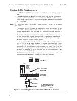
3.1 Installation of 4724
Figure 2 shows the placement of the 4724/4724-2 board in relation to the 4720.
1.
Very important! Remove power from the 4720 by disconnecting the AC power and bat-
tery.
2.
(Skip this step if you are installing a 4724 N) Carefully remove the 4720 control micro-
processor chip from its socket by inserting a flat-blade screwdriver under each end of the
microprocessor and slowly prying it out.
If you are installing a 4724-2 board that has a socket for this chip, press the chip into the
socket, notch facing downward. Observe proper polarity (it is the opposite of the other
large ICs).
3.
(Skip this step if you are installing a 4724 N) Insert the socket adapter into the 4720 con-
trol microprocessor socket. Pin 1 (marked on the adapter) goes into the upper left hand
corner of the socket. Make sure all pins are aligned. Press the adapter in, making sure the
adapter is fully seated (this requires a fair amount of pressure).
4.
Remove the lower left hand mounting screw from the 4720 panel. The screw will no
longer be used.
If an earth ground wire was attached at this screw, move the wire to another mounting
screw.
5.
Place the 4724/4724-2 circuit board over the pins on the socket adapter. The plastic
mounting bar should extend down over the mounting hole. Carefully press the 4724/4724-
2 onto the socket adapter, making sure the pins align with the rear entry connector. The
4724/4724-2 will rest level on the 4720 with the mounting hole aligned with the hole in
the mounting bar.
6.
Fasten the 4724/4724-2 to the 4720 by placing the long 6-32 Phillips screw (provided)
through the mounting bar into the mounting hole and tightening the screw.
7.
If you are expanding a Revision L (or earlier) 4720 board, you must remove the Model
4793 Dialer Chip from the Model 4720 board and replace it with the Model 4725 dialer
chip.
NOTE
Be sure to observe proper polarity when replacing the dialer chip.
8.
Reconnect power to the 4720 and turn on. “TIME 00:00” is the normal power-up display.
NOTE
The 4791 EEPROM (electrically erasable programmable read-only memory) chip on the 4720
is not used by the 4724/4724-2 and can be removed if desired. The 4724/4724-2 has its own
EEPROM.


