background image

Regency

® 

  Model 4724 Control Expander Installation Manual (P/N 150596-02, Rev. A)

    Revised 8/98

7

3.3.2

Suppliers of X-10 Modules

X-10 compatible modules can be obtained from Interactive Technologies, Inc. by contacting
ITI’s Order Entry Department at 800-777-4841.

3.4  Software Updates

If you are installing the 4724 on to a Revision L (or earlier) 4720 board and you want to print
zone numbers greater than 99 or use the Answering Machine Bypass feature, you will need to
replace the Model 4720 Dialer Microprocessor Chip (P/N 4793) with the Model 4725 Dialer
Chip. To order the 4725 Dialer Chip, contact ITI’s Order Entry Department at 800-777-4841.

Section 4: Touchpad Operation

4.1  Touchpad Designations

The 4724 allows the system to use both door/card access (up to 255 cards).

Each touchpad location (up to 15) has several programmable options. Touchpads designated as
door stations will allow codes to be used for door access. A programmable option allows sin-
gle-swipe access and disarm at door stations. The Exit feature on door access touchpads can be
programmed to generate a report and printout. Each card (code) must be assigned a group of
areas to which it is granted access. The card will work only at stations assigned to one or more
of the same areas.

Touchpads not selected as door stations will allow cards to be used for arming and disarming,
but not door access. Cards swiped at these stations will arm or disarm the system, depending
on the card's current privileges. Touchpads that are selected as door stations (not door only)
will allow codes to arm and disarm, if appropriately programmed. You can arm or disarm the
system by pressing the 

DOOR

 key and entering the appropriate code (usually Code 0 or Code

1). 

Touchpads designated as intercom stations will be able to use the Intercom features, but will
not have door access capabilities.

NOTE

Any station can access X-10 Modules or Model 4150 relays.

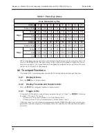
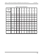
Alarms and touchpad troubles are annunciated by location. Panic keys report as separate zones
for each station. Duress alarms caused by entering the duress prefix also have a separate zone
ID for each touchpad Table 1, “Panic Key Zones,” lists the zone reported for each touchpad.

The zone numbers can be found from Table 1 or through the following formula:

     Zone = (Station ID #) x 4 + 145 + Keynumber

Keynumber 

1

 is for “POL,” 

2

 for “AUX,” and 

3

 for “FIRE.” The station ID is set for 0-15,

using the DIP switches on the back of each touchpad.

Summary of Contents for Regency 4724

Page 1: ...R E G E N C Y Model 4724 Control Expander Installation Manual Part Number 150596 02 Rev A Initial Release Date March 1995 Revised August 1998 ...

Page 2: ...nc ITI 1998 All rights reserved For reprints order manual 150596 02 Revision A T 6 5 1 7 7 7 2 6 9 0 F 6 5 1 7 7 9 4 8 9 0 Interactive Technologies Inc 2 2 6 6 S e c o n d S t r e e t N o r t h N o r t h S a i n t P a u l M N 5 5 1 0 9 2 9 0 0 Security Automation Fire Protection Access Control O E T H C N S G O L IE ...

Page 3: ... an experienced radio TV technician for help FCC Part 68 This equipment complies with part 68 of the FCC Rules Located on this equipment is a label that contains among other information the FCC registration number and the ringer equivalence number REN for this equipment If requested this information must be provided to the telephone company The REN is used to determine the maximum number of device...

Page 4: ...chpad Operation 7 4 1 Touchpad Designations 7 4 2 Touchpad Functions 8 4 2 1 Display Alarms 8 4 2 2 Display Troubles and Supervisories 8 4 2 3 Toggle X 10s 8 4 2 4 Display Events 9 4 2 5 Clear Events 9 4 2 6 Zone Display 9 4 2 7 Touchpad Display 9 4 2 8 Software Revision 9 Section 5 Area Control 9 5 1 Levels of Area Control 9 5 1 1 Simple System 9 5 1 2 Split Arming 9 5 1 3 Auto Open Close in a Mu...

Page 5: ...com Menu 8 34 8 10 Window Groups Menu 9 35 8 11 Messages Menu 10 35 8 12 Timers Menu 11 37 8 13 Key Options Menu 12 39 8 14 Key Zones Menu 13 40 8 15 Area Options Menu 14 42 8 16 Sensor Locations Menu 15 42 8 17 Programmable I O Statements Menu 16 42 8 17 1 Stepping Through the I O Program 43 8 17 2 Program Operations 43 8 17 3 Changing the Program 48 8 17 4 Leaving the I O Program 49 8 17 5 Facto...

Page 6: ... O Programming Procedure 5540 Software 56 Section 10 Walk Test Operation 61 Section 11 Summary of Revision H Enhancements 62 11 1 Auto Arm Disarm Enhancements 62 11 1 1 Open Close Groups 62 11 1 2 Exception Reporting 62 11 1 3 Open Close Trouble 62 11 1 4 Auto Open Close 62 11 2 Programmable I O Enhancements 62 11 2 1 New Programming Tools 62 11 3 New Options 63 11 4 Operational Changes 64 ...

Page 7: ...596 02 Rev A Revised 8 98 Figure 1 Connecting the Supervised Siren Module to the 4724 2 Figure 2 Model 4724 Installation 4 Figure 3 Model 4181 Connections 6 Figure 4 Built In Programmer Menu Structure 15 Figure 5 Auxiliary Devices 54 Figure 6 Connections to Terminals 15 16 and 18 55 ...

Page 8: ... Types 31 Table 8 Reporting Formats 33 Table 9 Factory Programmed Messages 36 Table 10 Test Day Choices 38 Table 11 Loop Response Times 41 Table 12 Zone Types 41 Table 13 Programmable Statement Options 44 Table 14 Status and Port Addresses 46 Table 15 Default I O Program 50 Table 16 Logical Operators 55 Table 17 Arithmetic Operators 56 Table 18 Programmable I O Output Labels Read Write 57 Table 19...

Page 9: ...arily for system users such as guests and baby sitters High security code option that requires selected system users to enter a second code to gain access to restricted areas 32 time windows for programming time restrictions and automatic arming and disarm ing times Time windows can also be used to activate X 10 or 4180 auxiliary outputs Holiday schedule can be programmed for 16 holiday dates Two ...

Page 10: ...programmed as not bypassable 5 For UL approved installations the Regency Supervised Siren Module must be wired to the 4724 To warn of a fire the module provides a UL temporal three siren that uses three dis tinctive repeating short beeps The module converts the panel s non supervised steady fire cadence to a supervised temporal three fire cadence This module also provides a dis tinctive supervised...

Page 11: ...ocket Pin 1 marked on the adapter goes into the upper left hand corner of the socket Make sure all pins are aligned Press the adapter in making sure the adapter is fully seated this requires a fair amount of pressure 4 Remove the lower left hand mounting screw from the 4720 panel The screw will no longer be used If an earth ground wire was attached at this screw move the wire to another mounting s...

Page 12: ...6 37 CONTROL CHIP ADAPTER P N 130315 OR 130316 PIN 1 UNDER 4724 4724 2 BOARD IF YOU ARE UPGRADING A 4720 REV M OR EARLIER BOARD Use 4724 Control Expander Use 130315 Adapter IF YOU ARE UPGRADING A 4720 REV N OR LATER BOARD Use 4724 2 Control Expander Use 130316 Adapter NOTES 1 4720 revision number on board itself 2 4724 uses 50747 series control chip 3 4724 2 uses 600 9384 series control chip MODEL...

Page 13: ...ine resistor Two 4110 expanders can be used for up to 120 additional serial zones Model 4125 Multiplexed Zone Expander The 4125 is enhanced by the 4724 to allow zones to be wired like 4720 internal zones Normally closed zones must have either a 15 K end of line resistor in series with the contact or they must be programmed as NO EOL YES Zones can be programmed as normally open and normally closed ...

Page 14: ...nchronized real time Plug the Model 4181 into a 120 VAC 60 Hz wall outlet to the panel Use a 4 wire Modular Phone Cable P N 130071 supplied to connect the 4181 to the modular jack P5 on the 4724 as shown in Figure 3 The maximum length of the cable is 20 feet The 4181 is optically iso lated from the power line WARNING The modular connectors on both the 4724 4724 2 and the 4181 must NOT be connected...

Page 15: ...st be assigned a group of areas to which it is granted access The card will work only at stations assigned to one or more of the same areas Touchpads not selected as door stations will allow cards to be used for arming and disarming but not door access Cards swiped at these stations will arm or disarm the system depending on the card s current privileges Touchpads that are selected as door station...

Page 16: ...sories 4 2 3 Toggle X 10s To toggle X 10 Modules on and off press a number from 11 42 then or CODE 2 followed by either 1 for on or 0 for off Numbers 11 26 activate modules 1 16 from House Code 1 Numbers from 27 42 activate modules 1 16 from House Code 2 The house codes for each section are programmed into the EEPROM electrically erasable pro grammable read only memory The display shows the actual...

Page 17: ... total system The Model 4724 allows an installation to be divided into up to eight areas There are two possible levels of system operation using areas split and simple system arming 5 1 Levels of Area Control 5 1 1 Simple System Area programming is used to divide system door access into separate areas Codes and touch pads for each area are programmed to determine who will to gain access at the tou...

Page 18: ...been wired regardless of the type of hardware used in each zone Chime zones only sound at touch pads in the same area Entry and exit zones are activated by area also There are separate entry exit timers for each area Each code can be assigned to any or all of the eight areas The code can be used only at touch pads that are also assigned to the same area or areas Each touchpad can be assigned to on...

Page 19: ...rogram mode at any time press MUTE twice until you no longer see the scrolling key prompts NOTE Do NOT follow the above procedure to program new secret codes for Code 0 and Code 1 Instead press 7 TEST see Section 7 6 of this manual 7 2 Stepping Through the Program By pressing the TEST key you can view the current option settings in a menu The option description appears on the top line followed by ...

Page 20: ...the right of the double lines 2 Press the digit to the left of the vertical double line in the same row 3 Press the digit above the horizontal double line in the same column The character will appear on the top line of the display Continue selecting characters this way until you have finished programming the message Pressing the STAT key will erase the last character you typed Pressing the BYPS ke...

Page 21: ...8 98 13 Table 2 Text and Characters Second Digit 0 1 2 3 4 5 6 7 8 9 First Digit 0 A B C D E F G H I 1 J K L M N O P Q R S 2 T U V W X Y Z or 3 a b c d e f g h i 4 j k l m n o p q r s 5 t u v w x y z 6 0 1 2 3 4 5 6 7 8 9 7 blank 8 _ 9 beep 0 05 sec beep 0 1 sec beep 0 5 sec beep 1 sec ...

Page 22: ...ay DATE with the current date on Line 2 enter DATE D for System Message 58 NOTE As you are programming you will see the shortened form of the message During normal use the actual non abbreviated message will appear 7 6 Programming Secret Codes To access the Secret Codes Menu press 7 TEST then enter Code 0 This menu is useful if you only want to change secret codes without going through all the opt...

Page 23: ...E 0 3 READY T SYSTEM BUSY 2 NOT READY 0 0 0 8 0 16 0 24 1 0 0 32 0 32 8 32 16 32 24 TIME OUT LONG DIST RING LISTEN DTMF DIAL QUIET PHONE TIME ONE WAY LINE TONE NEED D 2 MEM PH ONLY MEM D 1 MEM PH PHONE NUMBER 1 ACCT 1 REP ALRM 1 LINE 1 ONLY 4 LINE 2 ONLY 4 DIRECT LINE 4 INTERN ZONES EXP ZONES 1 RESD CODE 1 REP DLY BELL DLY NO SHUT DOWN COMP PH RETRY LINE 2 EX GROUND ST LINE MON ANSWER RING STORE O...

Page 24: ...le read only memory on which the options were originally programmed is no longer used C When the 4724 is installed options can be programmed using the 4724 s built in program mer accessed through any 4000 series touchpad or the Model 5540 Downloading Software The Model 5520 Desk Top Programmer cannot be used with the Model 4724 8 1 Time Windows Menu 0 The 4724 provides 32 available time windows ti...

Page 25: ...s for Code 0 installer s code and Code 1 main user s code functions because they are fixed Code 0 can always activate all features including the Hexiprogramming mode Code 1 can activate all control functions arming disarming bypassing etc and can program all user programmable options The secret codes for Code 0 and Code 1 are programmed in Test mode see Section 7 6 of this manual NUMBER 2 Select t...

Page 26: ...re the high security code for door access The high security code Code 255 is entered on the touch pad after the primary code CARD ONLY 2 NO The Card Only option allows a person to gain access to a door only by a card not by a touch pad WIN GRP 2 32 Select the time window group programmed in Window Groups Menu 9 during which each access code can be used To make it possible to use a particular code ...

Page 27: ...tment BACK DATE 00 00 Type in the month and day when you want the time to automatically be set one hour back for the fall daylight savings time adjustment NOTE To disable holidays or DST dates enter 0 0 0 0 for the date 8 5 System Menu 4 8 5 1 DEF MODE FORCE Default Mode This option is used to determine what the system will do when it times out of the Program mode This would occur after power has ...

Page 28: ...ES The dialer must always be selected for normal operation It can be disabled for troubleshooting or while training system users When the dialer is disabled there is no battery or AC detection PRINTER NO Select this option if you are using a Model 5255 On Site Printer or Model 5260 Printer Inter face ZONE EXP1 NO If at least one zone expander is to be used with the system this option must be selec...

Page 29: ...causes any zones that are not ready to be bypassed shunted when the system is armed Upon arming the 4724 will generate a CF Forced Closing Report NOTE Since force arming may automatically cause zones to be bypassed the Auto Bypass option should be selected if the Force Arm option is enabled INTR INTRU NO When this option is selected all interior zones will automatically be enabled when there is an...

Page 30: ...ses to the central station until the panel is armed AUT UNBYPASS NO This option will automatically unbypass the bypassed zones when the panel is disarmed to allow trouble conditions to be reported NOTE Since Force Arming may automatically cause zones to be bypassed the Auto Unbypass option should be selected if the Force Arm option is enabled BYPASS CODE NO Selecting this option makes it impossibl...

Page 31: ...PLIT BYPS NO Codes 2 through 144 can bypass only their corresponding zones Code 2 can bypass only Zone 2 Code 3 can bypass only Zone 3 etc NOTE Exception Code 0 and Code 1 can bypass all zones regardless of how this option is pro grammed CHIME PZT NO When this option is selected the chime tone will be heard at all touchpads assigned to the same area as the chime zone NOTE If this option is not sel...

Page 32: ...code This feature applies only to Code 2 through Code 255 When the Code 0 and Code 1 are used to program codes the digits of the code s will display This option is new with the 4724 2 Revision J2 or later RING B CLOSE NO Ring Back at Closing When this option is selected there will be a short bell test after kiss off when a Closing Report is sent BELL TST ARM NO Selecting this option causes a two s...

Page 33: ...Window 3 If someone arms the sys tem later in the morning before leaving the office for lunch for example and no one dis arms it by 2 00 PM the system will disarm automatically at 2 00 PM end of Time Window 4 Time Window 5 the system will NOT disarm automatically because another time win dow Time Window 6 in the open window group follows immediately If the system has not been disarmed manually by ...

Page 34: ... close NOTE In Revision H the above item is moved to Menu 14 Area options X 10 HC 1 A This option allows you to choose the house codes for the first 16 of the 32 allowable X 10 Modules There is a choice of 16 letters from which one house code can be selected for this option Enter the number next to the desired letters in Table 5 The house code you select should be different from those of any other...

Page 35: ...ill not try another time LINE 2 EN NO Line 2 Enable Select this option if you are using two phone lines requires the use of the Model 4175 Dual Phone Line Monitor GROUND ST NO Select this option if you are using a ground start telephone network LINE MON NO Select this option if you will be using the Model 4175 Dual Phone Line Monitor You can monitor Line 1 only if you do not have a second phone bu...

Page 36: ...ialing If you do not select this option the phone line will use rotary type dialing only NOTE If you have selected DTMF L1 the dialer will alternate between Touch Tone and rotary dial ing on subsequent attempts DTMF L2 NO If this option is selected Line 2 will use Touch Tone dialing DTMF ONLY NO If this option is selected Touch Tone dialing will be used any time the system is dialing out 8 7 Zone ...

Page 37: ...ones require a 15 K ohm EOL 24 hour trouble loop response is always 10 sec onds A 24 hour trouble will restore as soon as the loop is restored If you select DAY TRBL for a zone you must also select N C for that zone NOTE Do NOT pick both 24 HR TRBL and DAY TRBL N C 1 NO Select this option if the zone will be using normally closed contacts NOTE All N C zones require a 15 K ohm EOL N O 1 YES Select ...

Page 38: ...Select this option if the zone will be controlled by Entry Delay 2 INTERIOR NO Interior zones can be bypassed as a group using the INT key NOTE Select this option if the zone will be an interior zone BYPASS 1 NO Select this option if you want to be able to bypass shunt the zone If you do not select this option for a particular zone you will not be able to bypass that zone NOTE Fire zones must NOT ...

Page 39: ... as bedroom You may use any description that you want but the description must not be more than 16 characters in length including spaces See Section 7 5 of this manual for instructions on entering text SIL ALM 1 NO Silent Alarm When this option is selected alarm conditions will not be annunciated audibly but will be reported to the central station NOTE Holdup zones must be selected as SIL ALM REP ...

Page 40: ...six digits maximum REP ALRM 1 YES Select this option if you want alarms to be reported to Phone 1 REP TRBL 1 YES Select this option if you want trouble conditions to be reported to Phone 1 REP BYPS 1 NO Select this option if you want bypassed shunted zones to be reported to Phone 1 REP RSTR 1 Select this option if you want restorals to be reported to Phone 1 Restores will report only to the same n...

Page 41: ...eport event memory and zone numbers higher than 99 B Do not select SIA20 unless the receiver has a 9004I card The 9004 card can only accept SIA8 formerly SEA8 ATTEMPTS 1 1 Enter the number of attempts 1 15 that the communicator will try to report to this account number before switching to the next number typically one attempt LISTEN IN 1 0 Enter in seconds the length of time the central station ca...

Page 42: ...sing the Model 4140 Intercom Telephone Controller TIMEOUT 30s Enter in seconds the amount of time the intercom function will be active LONG DIST YES When this option is selected the telephone function can be used for long distance calls PHONE TIME NO Select this option if you want the Phone feature to have a limited length for calls The phone time out will be the same length selected for intercom ...

Page 43: ...Any of the 32 available time windows can be assigned in any combination to any of the 32 available window groups The user can program only the time windows themselves Window group assignments must be set up by the installer 0 0 0 In this step and the next three steps you ll assign time windows to Window Group 0 First select time windows in the range 0 7 by toggling the digits 0 through 7 The time ...

Page 44: ...hat option Table 9 Factory Programmed Messages Message Message Message Message 1 BYPASSED 30 MON 2 NOT READY 31 TUE 3 READY 32 WED 4 TROUBLE 33 THU 5 LOW BATTERY 34 FRI 6 SILENCED 35 SAT 7 OPEN 36 REPORTING 8 SERVICE 37 LISTENING 9 WALK TEST 38 UP DOWNLOAD 10 DATE 39 ZONE 11 TIME 40 PAPER 12 INTERCOM 41 _______ not used 13 PHONE 42 DATA LOST 14 DOOR 43 FAILED 15 ARMED 44 BATTERY 16 CODE2 45 AC 17 ...

Page 45: ...the supervision interval 2 24 Example If you enter 3 the system will check for supervisory transmissions from the RF transmit ters every three hours DOOR STRK 6 8s In this step you will program the length of time that the doorstrike stays activated 0 8 12 sec onds The display will always show 8 to indicate that the programmed length of time is 0 8 seconds times the number you select 4660 series to...

Page 46: ...s the length of the delay 0 255 before Auto Close occurs see Time Win dows Menu 0 The delay is added at the end of the auto close time period If you select 0 there will be no delay LOG 4150 0h Enter the number of hours between automatic printouts of the 4150 sensor readings 0 255 To disable the automatic printout function enter 0 AUTO TEST NO If you will be using one of the test features below you...

Page 47: ... RTCAL you must know how many seconds per day or week the clock gains or loses If you know the seconds per week divide by 7 to get the second per day 2 Multiply the per day number of seconds that the clock gains or loses by 6 07 to get the adjustment factor 3 If the clock is fast gains time subtract the adjustment factor from the current value of RTCAL 4 If the clock is slow loses time add the adj...

Page 48: ... is selected the High Security Code must be entered in addition to the secret code to gain door access DOOR ONLY 1 NO When this option is selected Touchpad 0 can be used only for door access not for other func tions such as arming and disarming STATION 2 Select the next touchpad for which options are to be programmed up to 15 touchpads 8 14 Key Zones Menu 13 STATION 0 Select the touchpad for which...

Page 49: ...ound REP DLY NO If you select this option alarms activated by this panic key will be reported after a pro grammed delay time The delay time is programmed in Timers Menu 11 BELL DLY NO Select this option to create a delay between the time an alarm condition is sensed by a zone of the specified type and the time the alarm bell is sounded NO SHUTD 1 NO If this option is selected the bell will not shu...

Page 50: ...ces to act as indicators of internal status conditions or to respond to the internal conditions in some way Sections 8 and 9 of this manual provide you with basic information on how to use the I O Pro gramming feature Regency s 47241 0 Application Programming Manual provides more in depth instructions To order the manual contact ITI s Order Entry at 800 777 4841 NOTE It is easier to Program the I ...

Page 51: ...he stack see statements 25 28 in the default program Table 15 Default I O Program located later in this section The 4724 can store up to 32 pieces of data on the stack before performing any operations Each opera tion is performed on the last one or two pieces of data that were put on top of the stack either by a GET statement or as the result of a previous operation 8 17 1 Stepping Through the I O...

Page 52: ... the negative of its value Next statement in program None 8 EQU Takes eight status bits that are grouped together from the 4724 s memory and place them on top of the stack NOTE This group of eight bits consti tutes a single item on the stack Next statement in program None 9 GET1 Takes a single status bit from the 4724 s memory and places it on top of the stack 0000 The address of the group of eigh...

Page 53: ...SEC TMIN THR MONTH MDAY to binary number before comparison Next statement in program None 19 2BCD Converts binary number to BCD Next statement in program None 20 Multiply MUL Multiplies two numbers Next statement in program None 21 2BIT Converts number 0 7 to bit in byte Next statement in program None 0 END Always the last statement in the program If an END statement is inserted it becomes the new...

Page 54: ...ET8 Area audible alarm AUXALM 26 1 GET1 Aux alarm activated AUXRLY 0 7 6D 0 7 GET1 GET8 4150 relay status AZONES 1 18 0 7 40a 41B 0 7 GET1 GET8 Armed zones BYPASS 25 5 GET1 Global zones bypassed CLGRP 1A 5 GET1 Close time window group DACT 68 2 GET1 Dialer active DOOR80 0 7 18 0 7 GET1 GET8 Toggle with 1 8 door DOOROPEN 0 15 491 4A0 2 GET1 Touchpad door open DOORRLY 0 15 491 7 4A0 7 GET1 PUT1 4660...

Page 55: ...GET1 4140 Phone mode REPORT 27 1 GET1 Reporting RLY 1 8E 0 7 GET1 PUT1 8 4180 Outputs Unit 1 P2 RLY 2 8F 0 7 GET1 PUT1 8 4180 Outputs Unit 1 P3 RLY 3 90 0 7 GET1 PUT1 8 4184 Outputs Unit 2 P2 RLY 4 91 0 7 GET1 PUT1 8 4184 Outputs Unit 2 P3 SCR 0 7 4B8 4BF 0 7 GET1 PUT1 8 Scratch locations See note SILENC 28 3 GET1 Silenced trouble SMKPWR EE 7 GET1 Smoke power on SPECL 28 1 GET1 Special alarm SYSTR...

Page 56: ...T1 28 0 PUT1 EE 4 2 The following statement will cause Terminal 16 on the 4720 to produce an active low output when ever there is an intrusion alarm in any area GET1 28 2 PUT1 EE 3 3 The following statement will cause the X 10 Module Address 1 from the first house code to be acti vated whenever Area 1 or a non area system is in entry or exit delay The module could then be used TSHUT F GET8 Bell sh...

Page 57: ...ts will turn on the X 10 Module when Entry mode in Area 1 is activated When ENTRY is not activated the X 10 Module follows Time Window 0 EXEC AENTRY 1 X10 1 0 1 EXEC NOT EXEC X10 1 0 WINSTAT 1 0 EXEC 1 8 17 4 Leaving the I O Program To exit the Programmable Statements Menu follow the following procedure Press the MUTE key The display will show SAVE NO To exit without saving the changes just press ...

Page 58: ...s of all eight outputs on 4180 Unit 1 P2 8 areas Generates an 8 bit binary constant with a value of 0 Match between all eight outputs of 4180 and 8 bit constant of 0 i e all eight areas disarmed Activates fifth output on 4180 Unit P3 29 30 31 32 33 GET1 27 7 GETC 0 EQU NOT PUT1 8F 50 Get the number of the current alarm type Get the value 0 zero Compare the alarm condition with 0 Turn on the output...

Page 59: ...uter can call it to download new program data or request status information from the panel After 10 rings the factory programmed value for the RINGS option the panel will answer the call and downloading will begin Subsequent Downloads If the Answer Ring option is still enabled the computer can call the panel as described above Downloading can also be initiated from a touchpad at the installation l...

Page 60: ...isplay will take up to four seconds to respond to the keys sent to the panel Examples Zone status Press N and the ENTER key to display not ready zones The zones are dis played along with their location text and area one at a time Set time 1 Press 9 T then enter a valid programming code such as Code 0 2 Press the ENTER key The display will show the set time display 3 Enter the digits for the time t...

Page 61: ...erface Menu appears press the A key to reprogram any of the options You will be prompted for an account number to edit 2 On the Edit Account Menu select the type of options you wish to program 3 When you finish programming the options on one of these menus press ESC to get back to the Edit Account Menu then choose another set of options to program 4 After you have reprogrammed all the options pres...

Page 62: ...ble output devices Figure 5 Auxiliary Devices Outputs are generated on three types of devices 1 Model 4720 panel Terminals 15 16 and 18 Terminals 15 and 16 are open collector outputs that sink current when activated negative voltage 12 VDC 50 mA maximum Terminal 18 functions as a current source when activated positive voltage 12 VDC 20 mA maximum Figure 6 shows how each of these terminals would be...

Page 63: ...nected to a LED you could program the system to light the LED if the printer ran out of paper You can also program a device to produce an output when a specific combination of conditions exists This is done by performing logical operations as shown in Table 16 The 5540 software and built in programmer are also capable of using arithmetic operators These opera tors are included in the Arithmetic Op...

Page 64: ...that cause the output to be generated Status Labels are assigned using the names shown in Table 20 Pro grammable I O Status Labels Read Only Some labels include a number in brackets This specifies one of the following several similar outputs or sets of outputs or one of several components of the installation e g zones or sets of components on which an internal condition can exist e g armed or disa...

Page 65: ...AM to 2 59 AM it will not go off between the two time intervals Table 18 Programmable I O Output Labels Read Write 1 Label2 Data Type Function RLY 4 BITS 4180 Status Relays TER16 BIT Output on Terminal 16 TER15 BIT Output on Terminal 15 TER18 BIT Output on Terminal 18 X10 4 BITS X 10 output bits SCR 8 NUMBER BITS User scratch area NOTE 1 An output can be generated written left side of if as a resu...

Page 66: ...se Code 2 X10 4 Outputs to X 10 Modules 9 16 of House Code 2 NOTE On connectors P2 and P3 of the 4180 the designation 0 refers to Pin 8 and the designation 7 refers to Pin 1 Table 20 Programmable I O Status Labels Read Only 1 Label2 Data Type Function AARMED 8 BIT Area n armed ACCAREA 8 BIT Window group status ACHIME 8 BIT Area n in Chime mode ACODE2 8 BIT Area n in Code2 mode AENTRY 8 BIT Area n ...

Page 67: ...it ICALL NUMBER Station number for intercom call ICOM BIT Intercom active INTBELL BIT Internal bell output on IRDY BIT Zones all ready INTR BIT Zone in trouble IZONES 18 BITS Zones that are interior bypassed KEYSUPR 16 BIT Touchpad supervise trouble LISTEN BIT Listen in active LOWBAT 18 BITS Zones with low battery LZNC 18 BITS Zone inputs below limit MDAY NUMBER Day of month MONTH NUMBER Month OPG...

Page 68: ...econds TSMOKE NUMBER Time left until smoke on in seconds TWKDAY NUMBER Day of week WARM BIT Watchdog reset occurred WALKTEST BIT Walk test mode WGRPSTAT 4 BITS Status of window groups WINSTAT 4 BITS Time window status bits YEAR NUMBER Year ZALM 18 BITS Zones in alarm or entry ZBYPASS 18 BITS Bypassed zones ZMEN 18 BITS Alarm memory zones ZTR 18 BITS Zones in trouble NOTE 1 A status condition can o...

Page 69: ...0 AEXIT 1 OR AENTRY 1 Section 10 Walk Test Operation The 4724 Walk Test mode allows you to test the system without causing Alarm Reports Fol low the procedure below to perform a Walk Test 1 Press 2 TEST followed by Code 0 or Code 1 2 The display will show either WALK TEST or your customized walk test message see Section 8 9 of this manual 3 Arm individual areas or the entire installation Then viol...

Page 70: ...the close window group the arming does not report to the central station When the arming occurs outside the windows the arming is reported to the central station Likewise Open Reporting is controlled by the open window group 11 1 3 Open Close Trouble This mode causes Trouble Reports to be sent when manual opening or closing does not occur during the specified open and close window groups The repor...

Page 71: ... 4 System Causes the arm menu to be active for all user open and close operations In previous versions system users assigned to one area only did not have access to the menu features By selecting this option all system users have access to the menu This option also applies to non split arm ing systems access is only granted to Area 1 in the menu Service Reminder mm dd 00 00 Menu 11 Timers 10 Syste...

Page 72: ...n this region 144 are the touchpad panic keys that use a similar formula Group Reporting Each area open close is reported as two events the user ID event OPen CLose nnn and the area ID event Open Close Group nnn In previous versions when more than one area was opened or closed at the same time the user ID event would only be sent once followed by multiple group ID reports Since most open and close...

Page 73: ...he delay touchpad beeps can be disabled by the Entry Exit PZT option Door Contact A delay was added to the door open timer when the door is first closed after legal access In door access applications where the door contact is used the door frequently closes and then bounces open enough for the contacts to reopen On older revisions the bounce open would cause a Door Forced Alarm On Revision H the d...

Page 74: ...ophe fault or negligence of the user or the original purchaser improper installation applica tion maintenance or use of Regency Product or other causes external to Regency Prod uct If you have a warranty claim please contact Customer Service at 1 800 777 4841 and request authorization to return the Regency Product Customer Service will issue you a Return Merchandise Authorization RMA number Return...

Page 75: ...sage 36 ACCAREA 46 ACCAREA 8 58 Access Menu 1 14 16 17 20 22 ACCESS WINDW NO 22 ACCOUNT 1 1 4 32 Accounts Menu 7 32 ACCT 1 000000 32 ACHIME 1 8 46 ACHIME 8 58 ACODE2 1 8 46 ACODE2 8 58 AENTRY 1 8 46 AENTRY 8 58 AEXIT 1 8 46 AEXIT 8 58 AINST 1 8 46 AINST 8 58 ALARM message 36 alarms audible alarm length 37 Auto Arms and 63 AUTO NO FRC NO 4 and 25 avoiding with zone type 12 31 BELL DLY NO and 41 by ...

Page 76: ... Auto Interior 64 Auto No Force 63 AUTO NO FRC NO 4 25 AUTO OC 42 Auto Open Close 10 62 AUTO OPEN NO 25 AUTO TEST NO 38 Auto Arm Disarm Enhancements 62 AUX CODE NO 24 AUX CONTROL NO 21 AUXALM 46 58 AUXILIARY message 36 AUXRLY 58 AUXRLY 0 7 46 AZONES 1 18 46 AZONES 18 58 B BACK DATE 00 00 19 BATTERY message 36 BCD A 56 BELL DLY 1 NO 32 BELL DLY NO 41 BELL TST ARM NO 24 BELL TST PU NO bell test at p...

Page 77: ...OOR DISARM NO 20 door event buffering 64 DOOR message 36 DOOR ONLY 1 NO 40 DOOR OPEN 60s 37 DOOR STRK 6 8s 37 DOOR 1 NO 40 DOOR 2 YES 17 DOOR80 59 DOOR80 0 7 46 DOOROPEN 59 DOOROPEN 0 15 46 DOORRLY 0 15 46 DOORRLY 16 59 DOORSUPR 59 DOORSUPR 0 15 46 Download when Armed 64 downloading information 51 software 51 verifying data 53 DTMF DIAL YES 34 DTMF L1 NO 28 DTMF L2 NO 28 DTMF ONLY NO 28 dumping ev...

Page 78: ...STANT message 36 instants and chimes 64 INTBELL 46 59 Intercom Menu 8 34 INTERCOM message 36 INTERCOM 1 NO 40 INTERCOM NO 21 interior followers INTR FLWRS NO 21 interior zones 30 INTERIOR NO 30 INTERN ZONES 16 28 INTR 59 INTR FLWRS NO interior followers 21 INTR LOCK NO 21 INTR UNTRU NO 21 INTRU 46 INTRUSION message 36 IRDY 59 ITI Order Entry 7 42 IZONES 1 18 0 7 47 IZONES 18 59 K KEY BEEP SPK NO 2...

Page 79: ...dule7 21 24 34 56 4175 Dual Phone Line Monitor 27 4180 Status Display Module 1 10 55 56 4181 Power Line Control Interface 1 6 39 55 4720 Control Communicator 1 5255 On Site Printer 20 5260 Printer Interface 20 5520 Desk Top Programmer 16 5540 Downloading Software 1 10 42 51 54 9000 Digital Alarm Receiver 23 34 9103 Line Card 34 MON message 36 monitoring sections 9 MONTH 47 59 MUST REP 1 YES 33 N N...

Page 80: ...ES 33 REP TRBE 1 YES 32 REP DLY 1 NO 31 REP PR EXIT NO 20 REPORT 47 60 report openings closings 23 reporting exceptions 62 groups 64 REPORTING message 36 requirements UL 2 RESD CODE 1 0123 28 RESD CODE 2 0223 29 resistors end of line type 29 response times loops 29 RESTRICTED message 36 RETRY NO 27 Revision H Options 42 RF SUPRV 24h 37 RING B CLOSE NO ring back at closing 24 RING 12345675 35 RLY 1...

Page 81: ...me Windows Menu 0 16 17 18 35 38 TIMEOUT 30s 34 Timers Menu 11 16 22 37 41 TKEY 47 TMIN 47 60 tools programming 62 TOPEN 60 TOPEN 0 15 47 TOTAL ATTM 10 28 touchpads displaying locations 9 functions 8 maximum number supervised 23 operation 7 programming options for 7 viewing status on 52 TREE 47 60 TROUBL 47 60 TROUBLE message 36 troubles displaying 8 open close type 62 TRY AGAIN message 36 TSEC 47...

Page 82: ...and 7 status and port addresses 48 X 10 HC 1 A 26 X 10 HC 2 B 26 X10 1 48 58 X10 1 0 58 X10 1 1 58 X10 2 48 58 X10 3 48 58 X10 4 48 57 58 Y YEAR 60 Z ZALM 1 18 0 7 48 ZALM 18 60 ZBYPASS 1 18 0 7 48 ZBYPASS 18 60 ZMEN 1 18 0 7 48 ZMEN 18 60 ZONE EXP1 NO 20 ZONE EXP2 NO 21 zone expanders 5 ZONE message 36 Zone Options Menu 6 28 37 42 ZONE 1 29 ZONE 2 32 zones area assignments and 10 avoiding alarms ...

Reviews: