


Regency
®
Model 4724 Control Expander Installation Manual (P/N 150596-02, Rev. A)
Revised 8/98
55
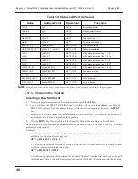
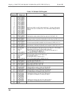
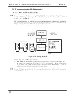
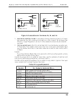
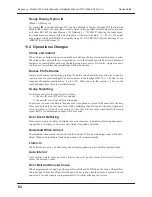
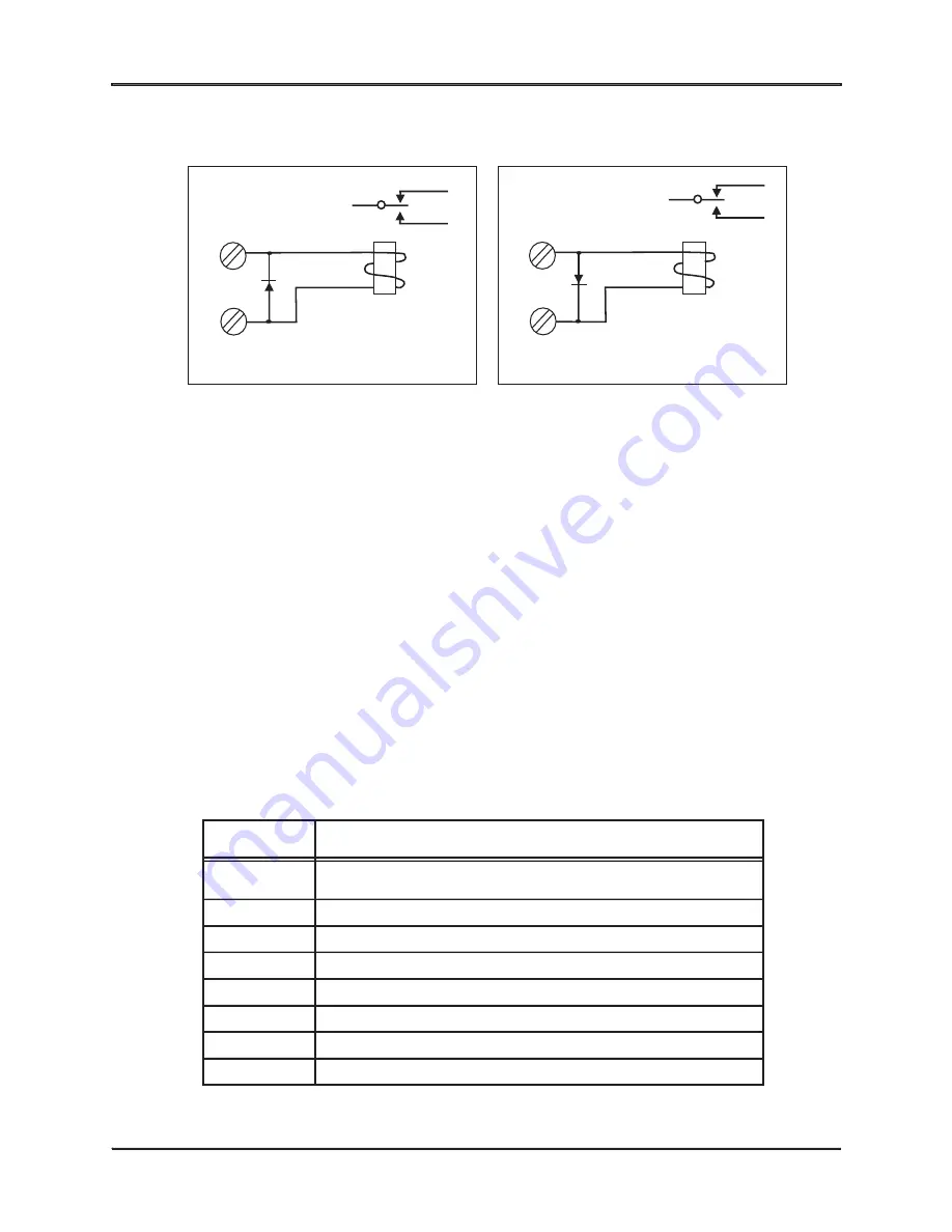
Figure 6: Connections to Terminals 15, 16, and 18
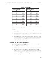
2.
Model 4180 Status Display Module. Two modules can be daisy-chained to provide up to 32 outputs.
Each module has four relays, which can be activated by any of the 16 outputs. The top three sections
of Table 16, “Output Designations,” (Section 9.5 of this manual) show which relay label identifies
each output
3.
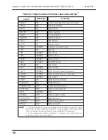
X-10-Compatible Modules. The 4724 with the Model 4181 Power Line Interface can control up to
32 X-10 Modules. These modules, which come in many forms, can be used to control lights or appli-
ances. The fourth section of Table 19 (later in this section) shows which X-10 label refers to each X-
10 Module.
Example:
If one of the 4180 Status Display Relays were connected to a LED, you could program the system to
light the LED if the printer ran out of paper.
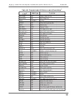
You can also program a device to produce an output when a specific combination of conditions exists.
This is done by performing logical operations, as shown in Table 16.
The 5540 software and built-in programmer are also capable of using arithmetic operators. These opera-
tors are included in the “Arithmetic Operators” table below:
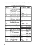
Table 16: Logical Operators
Operator
“
On
”
Output is Generated When…
A AND B
Both Condition A and Condition B are in effect
(for example, Area 1 is armed and Area 2 is armed).
A OR B
Either A or B or both is in effect.
A XOR B
Either A or B is in effect, but not both.
NOT (A)
The specified condition is not in effect.
A = B
A and B are in the same state (in effect or not in effect).
EQZ (A)
When A is zero (uses less memory than (A=0))
A > B
If A is greater than B.
A < B
If A is less than B.
GROUND
TERMINAL 18
9
-
+
12 VDC
20 MA MAX.
IN4001
8457G17A.DSF
ACC. POWER
TERMINAL 15 OR 16
5
+
-
12 VDC
50 MA MAX.
IN4001